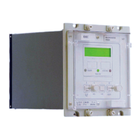
VCG202/EN M/H11
Technical
Setting Symbols KVGC adjustment range In steps of
Tap change indication time t Tap change 1 – 3 secs 0.1 secs
5.1.1 Setting voltage (Vs)
The setting voltage can be selected between 90 and 139V in 0.1 volt steps.
The relay compares the system input voltage with this setting voltage and provides raise
or lower signals to the tap changer to control the system voltage to be within the set
deadband limits.
5.1.2 Deadband (dVs)
The deadband limits are defined as dVs % of Vs setting and are dependent on the tap
step increment of the regulating transformer. Typically, dVs % = ±1% for an average tap
step increment of 1.4% on the transformer. The deadband can be set between 0.5% to
20% of Vs.
5.1.3 Initial time delay setting (tINIT)
The time delay to initiate a tap change sequence is set by the initial time delay setting
between 0 and 300 seconds. A software function link (CTL link 2) determines setting of
either definite or an inverse time characteristic.
Selection of a ‘definite’ initial time delay provides a fixed definite time delay before
initiating a tap change and is independent of the voltage deviation. Whereas, selection of
an ‘inverse’ characteristic gives a time delay inversely proportional to the voltage
deviation from the setting voltage, Vs.
For inverse characteristic the initial time delay setting defines the operating time delay at
the edge of the deadband, N=1. Larger voltage deviations give corresponding faster
operating times as shown by the inverse characteristic in Appendix 1. The general
expression for inverse time curve:
t = k + [(initial time delay setting) x (1/N)]
where k = 0.5 for initial time delay setting -20s
= 0 for initial time delay setting >20s
N indicates % deviation from Vs in multiples of dVs % and is calculated as:
N =
Vreg - Vs
Vs
*100
dVs %
where Vreg = Voltage to be regulated
Vs = Voltage setting
dVs % = Dead band
5.1.4 Inter-tap delay (tINTER)
Where a multiple tap change sequence is required to bring the voltage back to within the
deadband limits then the time delay between successive tapping outputs can be set
between 0 and 120 seconds. This is normally set to be slightly longer than the operating
time of the tap changer mechanism.
The inter-tap delay starts after the first tap pulse has elapsed. When the initial time has
elapsed the output continues to give pulsed closure for tap pulse duration at intervals set
by the inter-tap delay. Setting the inter-tap delay to 0 seconds results in a continuous
output indicated by continuously illuminated ‘Control LED’.

 Loading...