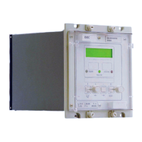
VCG202/EN M/H11
Technical Manua
KVGC20
3.4.14
Setting output masks 29
3.4.15 Resetting values 29
3.4.16 Resetting CONTROL LED indication 29
3.5 External connections 29
3.5.1 Auxiliary supply 30
3.5.2 Logic control inputs 31
3.5.3 Analogue inputs 32
3.5.4 Output relays 32
3.5.5 Setting the relay with a PC or Laptop 32
3.6 Alarm flags 33
4. APPLICATION OF CONTROL FUNCTIONS 34
4.1 Configuring the relay 34
4.2 Changing the configuration of the relay 34
4.2.1 SYSTEM DATA (SD) 34
4.2.2 Logic links (LOG) 35
4.2.3 Control links (CTL) 36
4.2.4 Default output relays 36
4.3 Setting group selection 36
4.4 ApplicatIons 37
4.4.1 Introduction 37
4.4.2 Basic requirements 37
4.4.3 Operating time delay 37
4.4.3.1 Initial delay (tINIT) 38
4.4.3.2 Definite/Inverse time characteristics 38
4.4.3.3 Intertap Delay 39
4.4.3.4 Tap Pulse Duration (tPULSE) 39
4.4.4 Operating Sequences 39
4.4.4.1 Method 1 39
4.4.4.2 Method 2 39
4.5 Line drop compensation 40
4.6 Auto, manual and remote operation modes 41
4.6.1 Remote change of operating mode 42
4.6.2 Manual change of operating mode via logic input 42
4.7 Paralleled transformers 42
4.7.1 Master-Follower schemes 43
4.7.2 Instability of individually controlled parallel transformers 44
4.7.2.1 Runaway 44
4.7.2.2 Effect of circulating current on LDC 45
4.7.3 Negative reactance compounding 47
4.7.4 Circulating current control 50
4.7.4.1 Independent/parallel control 51
4.7.4.2 Circulating current control with LDC 52
4.8 Supervision functions of a VRR 58
4.8.1 Runaway protection 58
4.8.2 Undervoltage detection (V<) 58
4.8.3 Undervoltage blocking (V<<) 59
4.8.4 Overvoltage detection (V>) 59
4.8.5 Overcurrent detection (I
L
>) 59
4.8.6 Undercurrent detection (I
L
<) 59
4.8.7 Circulating current detection (IC>) 59
4.8.8 Reverse current detection (I rev) 59
4.9 Tap position indication 59

 Loading...