VCG202/EN M/H11
Technical
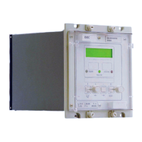
3.2.1 Frontplate layout
Figure 1: Front plate layout
The front plate of the relay carries a liquid crystal display (LCD) on which data such as
settings, measured values and information for the control conditions can be viewed. The
data is accessed through a menu system. The four keys [F]; [+]; [–] & [0] are used to
move around the menu, select the data to be accessed and enter settings. Three light
emitting diodes LEDs indicate alarm, healthy and control conditions.
A label at the top corner identifies the relay by both its model number and serial number.
This information uniquely specifies the product and is required when making any enquiry
to the factory about a particular relay. In addition, there is a rating label in the bottom
corner which gives details of the auxiliary voltage and current ratings. Two handles, one
at the top and one at the bottom of the front plate, will assist in removing the module from
the case.
3.2.2 LED indications
The three LEDs provide the following functions:
GREEN LED Labelled as ‘HEALTHY’ indicates the relay is powered up and running. In
most cases it follows the watchdog relay.
YELLOW LED Labelled as ‘ALARM’ indicates alarm conditions that have been detected
by the relay during its self checking routine or supervision control. The
alarm lamp flashes when the password is entered (password inhibition
temporarily overridden).
RED LED Labelled as ‘CONTROL’ indicates a tap change that has been issued by
the relay and is lit for a period, tPULSE. When lit permanently it indicates
tap change operation (Raise and Lower) is blocked or the inter-tap delay
is set to zero. The control lamp flashes to indicate that one or more
system fault indications are present.

 Loading...