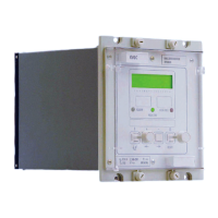
Manual
KVCG202/EN M/H
6.4.5 Overvoltage detection (V>)
The overvoltage detector will block operations that raise the voltage, to prevent excessive
voltage on busbars local to the transformer.
V> output relay allocated in the relay mask will pick up the overvoltage detection
condition to give the alarm indication.
The pick-up/drop-off differentials on the overvoltage detector will be –1% of the threshold
setting.
6.4.6 Circulating current detection (
Ic>)
The circulating detector (
IC>) limits the tap differences between parallel transformers. In
the event of excessive circulating current over a certain period (t
IC), the Ic detector will
be used to internally block the relay for both ‘Raise’ and ‘Lower’ operations.
Ic> output relay allocated in the relay mask will pick up the excessive circulating current
condition to give the alarm indication. If the logic link [LOG2] is set to ‘1’,
the alarm condition will also cause the blocking of the tap change control operation.
The pick-up/drop-off differentials on the excessive circulating current is –5% of the
threshold setting.
6.4.7 Overcurrent detection (
IL>)
If the load current (
IL) through a transformer exceeds the threshold setting, IL> output
relay allocated in the relay mask will pick up the excessive load current condition to give
the alarm indication. If the logic link [LOG3] is set to ‘1’, the operation of tap changer will
be inhibited for fault or overload current through the transformer.
The pick-up/drop-off differentials on the overcurrent detector is –5% of the threshold
setting.
6.4.8 Undercurrent detection (
IL<)
If the load current (
IL) through a transformer drops below the threshold setting, IL<
output relay allocated in the relay mask will pick up the insufficient load current condition
to give the alarm indication. If the logic link [LOG8] is set to‘1’, the operation of tap
changer will be inhibited. The pick-up/drop-off differentials on the undercurrent detector
is +5% of the threshold setting.
6.4.9 Reverse current blocking (
Irev)
If the load current
IL) is in reverse direction, Irev output relay allocated in the relay mask
will pick up the reverse current condition to give the alarm indication. If the logic link
[LOG6] is set to ‘1’, the operation of tap changer will be inhibited and the delay timer will
be reset instantaneously.
If the system link (SD6) is set to ‘1’ then the relay will use group 2 settings.
6.4.10 Run-Away
Run-Away is the feature that monitors the tap position and checks that an authentic tap
change signal has been initiated. An alarm is initiated if:
- tap changer operates in the absence of an initiation signal or
- tap changer operates in a direction which causes the voltage to move further away
from the desired voltage Vs.
Blocking condition is initiated to inhibit any further tap changes if logic link [LOG7] is set
to ‘1’.

 Loading...