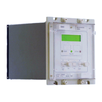
Manual
KVCG202/EN M/H
the tap changers are forced to be in step with each other if the compensating voltage, Vc,
is large enough to take the regulated voltage outside the deadband.
The circulating current inputs from the line CTs for the KVGC202 are terminals 23-24 for
1A rated CTs and 25-26 for 5A rated CTs. The pilot wires are connected between
terminals 21-22, see Figure 5 Appendix 3.
The requirement of a pilot wire loop usually limits the use of this scheme to control
transformers which are paralleled on a local site. Where this is not the case then reverse
reactance schemes must be used.
Figure 21: Pilot Method of Circulating Current Control
Figure 22: Circulating Current Compensation
4.7.4.1 Independent/parallel control
Where transformers connected in parallel are controlled using the minimum circulating
current principle, independent operation is selected by shorting the interconnecting pilot
wires as in Figure 23.

 Loading...