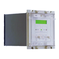
Manual
KVCG202/EN M/H
9.1.7 Test block
If the MMLG test block is provided, the connections should be checked to the scheme
diagram, particularly that the supply connections are to the live side of the test block
(coloured orange) and with the terminals allocated odd numbers (1, 3, 5, 7 etc.). The
auxiliary supply is normally routed via terminals 13 (+) and 15 (–), but check against the
schematic diagram for the installation.
9.1.8 Insulation
Insulation tests only need to be done when required.
Isolate all wiring from the earth and test the insulation with an electronic or brushless
insulation tester at a dc voltage not exceeding 1000V. Terminals of the same circuits
should be temporarily strapped together.
The main groups on the relays are given below but they may be modified by external
connection as can be determined from the scheme diagram.
a) Current transformer circuits.
b) Voltage transformer circuits.
c) Auxiliary voltage supply.
d) Field voltage output and opto-isolated control inputs.
e) Relay contacts.
f) Communication port.
g) Case earth.
Note: Do not apply an insulation test between the auxiliary supply and
the capacitor discharge terminals because they are part of the
same circuit and internally connected.
9.2 Commissioning test notes
9.2.1 Equipment required
For KVGC202 relays the following equipment is required:
AC auxiliary supply suitable to supply a 30VA load. Frequency of 50/60Hz.
Multi-finger test plug type MMLB01 for use with test block type MMLG.
Continuity tester.
Three phase voltage supply 440V.
440/110V star/star phase shifting transformer AC voltmeter 0 – 440V
DC voltmeter 0 – 250V
AC Voltmeter 0 to 440V range
AC multi-range ammeter
Suitable non-inductive potentiometer to adjust polarising voltage level.
Interval timer
Phase angle meter or transducer. If necessary suitable current shunt(s) for use with the
phase angle meter.
A portable PC, with suitable software and a KITZ101 K-Bus/IEC 60870-5 interface unit
will be useful but in no way essential to commissioning.

 Loading...