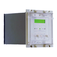
Manual
KVCG202/EN M/H
- load current setting (
IL)].
9.7 Supervision and monitoring
9.7.1 Undervoltage detector (V<)
The relay should be commissioned with the settings calculated for the application.
The undervoltage detector blocks ‘Lower’ operations to prevent lower voltage on busbars
local to the transformer.
[Before making the following changes note the settings for: initial time delay setting
(tINIT), intertap delay (tINTER), undervoltage setting (V<).
Set the:
- initial time delay setting (tINIT) to 2 seconds,
- intertap delay (tINTER) to 0 seconds,
- undervoltage setting (V<) to 80V to 130V].
Set the relay output mask to operate undervoltage detector ‘V<‘, these contacts should be
open. ‘Raise volts’ contacts should also be open.
Apply 95% of the system voltage setting to input (terminals 17 & 18). After the initial time
delay, the ‘CONTROL’ LED should illuminate, the ‘Raise volts’ contacts should close, and
the ‘Lower volts’ contacts should open.
Slowly reduce the applied voltage and measure the voltage at which the undervoltage
relay contact ‘V<‘ closes.
Check the measured voltage is within (V<) –2% of setting.
Check the ‘Lower volts’ contacts remain open and ‘Raise volts’ contacts remain closed.
Increase the applied voltage above Vs setting and ensure ‘Lower volts’ contact closes
and ‘Raise volts’ contact opens.
[Restore the following settings:
- initial time delay setting (tINIT),
- intertap delay (tINTER),
- undervoltage setting (V<)].
9.7.2 Overvoltage detector (V>)
The relay should be commissioned with the settings calculated for the application.
Operation of the overvoltage detector will block ‘Raise’ operations, to prevent excessive
voltage on busbars local to the transformer.
Before making the following changes note the settings for: initial time delay setting
(tINIT), intertap delay (tINTER), Overervoltage setting (V>).
Set the:
- initial time delay setting (tINIT) to 2 seconds,
- intertap delay (tINTER) to 0 seconds,
- overvoltage setting (V>) to 105V to 160V].
Set the relay output mask to operate over voltage detector ‘V>’ contacts. The contacts
should be open.
Apply 105% of the system voltage settings to input (terminals 17 &18). After the initial
time delay the, ‘CONTROL’ LED should illuminate. The ‘Lower volts’ contacts should
close and the ‘Raise volts’ should open.

 Loading...