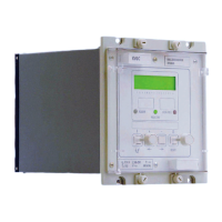
Manual
KVCG202/EN M/H
There are two setting groups available, this allows the user to set Group 1 to normal
operating conditions while Group 2 can be set to cover abnormal operating conditions.
The factory settings can be changed to the customer settings by referring to the
instructions detailed in Chapter 3 Section 3.4.
The commissioning engineer should be supplied with all the required settings for the
relay. The settings should be entered into the relay via the front keypad or using a
portable PC with a K-Bus connection. Some settings are password protected, in these
cases the password will also be required.
9.4.1 Selective logic functions to be tested.
For the selective logic checks only the features that are to be used in the application
should be tested. Relay settings must not be changed to enable other logic functions that
are not being used to be tested. However to conduct some tests some of the settings
may require adjustments. The commissioning engineer should ensure that after
completing all tests that all required settings are set for the relay.
If an output relay is found to have failed, an alternative relay can be reallocated until such
time as a replacement can be fitted. Refer to Chapter 3 Sections 3.4.13 & 3.4.14 for how
to set logic and relay masks.
Selective logic functions Test
Regulated Voltage setting V
S
and Dead Band Setting dV
S
6.1
Load Shedding/Boosting 6.2
Integrated timer 6.3
Line drop compensation 6.4
Under Voltage Detector (V<) 7.1
Over Voltage Detector (V>) 7.2
Load Current Detector (IL)
7.3
Under Voltage Blocking (V<<) 7.4
Circulating Current Detector (I
C
)
7.5
RunAway Protection 7.6
Table 4
Selective logic features listed below require K-Bus remote commands and are not
covered by the commissioning instructions:
- Remote setting change
- Remote group change
- Remote load shedding/Boosting control.
Note: The above accuracy limits make no allowance for instrument errors
and possible poor waveform which may be experienced during
commissioning.
9.5 Measurement checks
All measurements can be viewed from the [0200 MEASURE] menu heading on the LCD.
9.5.1 Current measurement
To test the relay current measurement functions inject a known level of current into each
current input in turn and monitor the values in the [0200 MEASURE] menu.
9.5.2 Voltage measurement
To test the relay voltage measurement functions apply a known level of voltage across
the system voltage input and monitor the values in the [0200 MEASURE] menu.

 Loading...