VCG202/EN M/H11
Technical
9. COMMISSIONING, PROBLEM SOLVING AND MAINTENANCE
9.1 Commissioning preliminaries
The safety section should be read before commencing any work on the equipment.
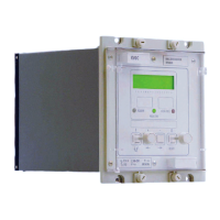
When commissioning a KVGC202 relay for the first time, the engineers should allow an
hour to get familiar with the menu. Please read Chapter 3 Section 3.3 which provides
simple instructions for negotiating the relay menu using the push buttons [F] [+] [–] and [0]
on the front of the relay. Individual cells can be viewed and the settable values can be
changed by this method.
If a portable PC is available together with a K-Bus interface unit and the Courier Access
software, then the menu can be viewed a page at a time to display a full column of data
and text. Settings are also more easily entered and the final settings can be saved to a
file on a disk for future reference or printing a permanent record. The instructions are
provided with the Courier Access software.
9.1.1 Quick guide to local menu control
With the cover in place only the [F] and [0] push buttons are accessible, so data can only
be read or flag and counter functions reset. No control or configuration settings can be
changed. Refer to Chapter 3 Section 3.4.1 for a quick guide to the menu controls.
9.1.2 Terminal allocation
Reference should be made to the appropriate connection diagram shown elsewhere in
this manual. Chapter 3 Section 3.5 gives further information on the external connections
to the relay. Reference should also be made to the relay masks to identify which
functions are allocated to which outputs.
9.1.3 Electrostatic discharge (ESD)
See recommendations in Chapter 2 of this user manual before handling module outside
its case.
9.1.4 Inspection
Loosen the four cover screws and remove the cover, the relay can now be withdrawn
from its case. Carefully examine the module and case to see that no damage has
occurred since installation and visually check the current transformer shorting switches in
the case are wired into the correct circuit and are closed when the module is withdrawn.
Check that the serial number on the module, case and front plate are identical and that
the model number and rating information are correct.
Check that the external wiring is correct to the relevant relay diagram or scheme diagram.
The relay diagram number appears inside the case on a label at the left hand side. The
serial number of the relay also appears on this label, and on the front plate of the relay
module. The serial numbers marked on these two items should match; the only time that
they may not match is when a failed relay module has been replaced for continuity of
protection.
With the relay removed from its case, ensure that the shorting switches between
terminals listed below are closed by checking with a continuity tester.
Terminals: 21 and 22; 23 and 24; 25 and 26; 27 and 28.
9.1.5 Earthing
Ensure that the case earthing connection, above the rear terminal block, is used to
connect the relay to a local earth bar and where there is more than one relay the copper
earth bar is in place connecting the earth terminals of each case in the same tier
together.
9.1.6 Main current transformers
DO NOT OPEN CIRCUIT THE SECONDARY CIRCUIT OF A LIVE CT SINCE THE HIGH
VOLTAGE PRODUCED MAY BE LETHAL TO PERSONNEL AND COULD DAMAGE
INSULATION.

 Loading...