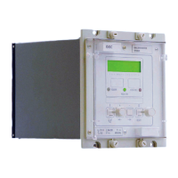
VCG202/EN M/H11
Technical
6.4.11 Tap position indication
The relay provides an indication of the actual tap position. If the tap position read
exceeds the minimum (Tp<) and maximum (Tp>) thresholds, an output relay (TapLimit)
allocated in the relay mask operates to give an alarm indication.
6.4.12 Tap change operations counter
The relay provides an indication of the maximum number of counts of the tap changer
operations (TotalOps). A relay totalises the number of tap change operations every time
the relay initiates a tap change signal to the tap changer (RaiseV or LowerV) due to
voltage deviation.
When the number of tap change operations exceeds a preset value, TotalOps output
relay allocated in the relay mask will initiate an alarm condition. If link [LOG4] is set to ‘1’,
the tap change operation is blocked and hence putting the relay out of service.
6.4.13 Frequent operations monitor
The relay also provides the tap changer maintenance mechanism to monitor the frequent
operations (FreqOps) of the tap changer operations. A counter is incremented as soon
as the change in tap position is detected and the maintenance timer is incremented by
the time elapsed since last function call in 10ms periods.
When the number of tap change operations exceed a certain threshold over a preset time
period, FreqOps output relay allocated in the relay mask will initiate an alarm condition. If
logic link [LOG5] is set to ‘1’ and the relay is set in ‘Auto’ mode, any further tap change
operations is blocked and hence putting the relay out of service until the alarm condition
is cleared by pressing the [0] key.
The values of the timer and counter can be reset to zero when any of the following has
occurred:
Tap change is blocked
After the events have been recorded after every elapse of time period
The maintenance timer has exceeded the preset time period
Alternatively, a reset cell command can be sent via the serial communication port. These
cells are password protected and cannot be reset if the password has not been entered.
6.4.14 Tap changer failure mechanism
The Tap Changer Failure feature is provided to detect failure of a tap changer to respond
to Raise/Lower commands of the relay.
Tap changer failure is detected by checking if the regulated voltage fails to come within
the deadband limits within the tFAIL time delay in response to a valid raise/lower
command. If a tap change failure is detected the TapFail output relay allocated in the
Relay Mask picks up to give an alarm indication, tap changing is blocked and the flags
which indicate that a tap change is expected are reset. If Logic Link [LOG1] is set to ‘1’
and the relay is set in ‘AUTO’ mode, any further tap change operations are blocked and
hence put the relay out of service until the alarm condition is cleared. There is no direct
inhibition of the alarm indication except by non selection in the output mask. If [LOG1] is
set to ‘0’ the alarm and block will be reset when the voltage is restored to within the
deadband limits.
The tap fail delay timer is reset instantaneously when the voltage is restored to within the
deadband limits.

 Loading...