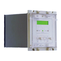
Manual
KVCG202/EN M/H
5.1.5 Tap pulse duration (tPULSE)
The tap pulse duration can be set between 0.5 to 5 seconds. It is initiated to ‘Raise volts’
or ‘Lower volts’ during multiple tap change sequence.
5.1.6 Line drop compensation (Vr and Vxl)
The resistive and reactive controls are set such that the voltage at a point remote to the
tap changing transformer can be regulated for varying load conditions.
The resistive line drop compensation can be set between 0 and 50 volts at rated current.
The reactive line drop compensation can be set between -50 to +50 volts at rated current.
Vr =
3.Ip.RL
VT ratio
Vr =
3.Ip.XL
VT ratio
Where Ip = primary rated current of line CT
RL = resistive component of line impedance
XL = reactive component of line impedance
VT ratio= ratio of primary to secondary voltages of line VT
Setting the Vxl to –ve value allows selection of reverse reactance for control of circulating
current where transformers are connected in parallel. For reverse reactance control the
settings are now as below:
Vxl (reverse) =
3.Ip.Xt
VT ratio
Where Xt = reactance of transformer
Now Vr =
3.Ip
VT ratio
(RL Cos φ + XL Sin φ + Xt Sin φ
Where Cos φ = power factor of load
Note : The setting PF angle setting in the control column should be set to
(Cos φ) in this case.
The above shows that the effective Vr compensation can vary significantly for varying
power factors. Reverse reactance control of parallel transformers is used where
transformers are dissimilar or at different locations and the power factor variation is not
too great.
5.1.7 Circulating current compensation (Vc)
An alternative method of achieving stable control of parallel transformers is to minimise
the reactive circulating current
Ic by the introduction of a parallel compensation voltage
Vc, which is proportional to
Ic. To establish the value of Ic, a pair of pilots must be
connected between the KVGC’s on the parallel transformers (see Figure 2 in Appendix
3).
The Vc setting can be set between 0 and 50 volts for reactive rated current applied to the
circulating current inputs. The Vc setting is determined during commissioning procedures
such that optimum stability is obtained for parallel transformers.
An approximate setting is given by:
Vc =
3.Ip.Xt
VT ratio
Circulating current control using Vc setting allows both resistive and reactive components
of line drop compensation to be utilised and is independent of power factor variations.

 Loading...