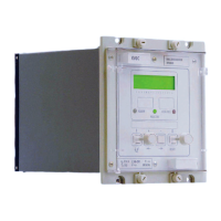
VCG202/EN M/H11
Technical
Open switch S2 and reduce the voltage to 90% of Vs using a decade resistance box and
reset the timer. Close switch S2 and measure the initial time delay. The ‘Lower volts’
relay output contacts should close after the initial time has elapsed.
Measured time should lie between 29.85s and 30.15s (ie. tINIT ±0.5%) or 15ms to 35ms
whichever is greater.
[Restore the following settings: initial time delay (tINIT), inter tap delay (tINTER)].
9.6.3.3 Inverse time delay
The time delay to the first tap change initiation (initial delay) commences when the
voltage goes outside the deadband. When the voltage is within the deadband the timer
will reset at the same rate it operates. To test the initial delay timer it is necessary to
reset the timer. This is accomplished by swinging the voltage through the deadband from
the side opposite to that which it will go to when timing is initiated.
For this test the initial time delay is dependant on several factors; how far away the
voltage deviates beyond the dead band edges, dead band setting and initial time delay
setting.
The general expression for inverse time curve:
t = k + [(initial time delay setting) x (1/N)]
where
k = 0.5 for initial time delay setting -20s
= 0 for initial time delay setting >20s
N indicates % deviation from Vs in multiples of dVs% and is calculated as:
N =
{Vbc - Vs}
Vs
* 100
dVs%
where Vbc = Voltage to be regulated
Vs = Voltage setting
dVs = Dead band
Calculate the value of N
When Vbc = 105%Vs
Calculate the expected time t
When k = 0
Check that the initial time delay characteristic is set to ‘Inverse’ [0301 CONTROL].
[Before making the following changes note the settings: dVs, and initial time delay (tINIT)
Set dVs to 1%, and the initial time delay (tINIT) to 30 seconds.
Therefore N = 5 and t = 6 seconds]
Set the timer to start from closing of switch S2 and stop on closing of the lower volts
contact ‘Lower volts’.
Close switch S2, adjust the applied voltage to 105% of Vs.
The system voltage (Vs). Reset the timer.
Open switch S2 and adjust the voltage to 100% of Vs using a decade resistance box and
reset the timer. Close switch S2 and measure the initial time delay. The ‘Lower volts’
relay output contacts should close after the initial time has elapsed.
Measured time should lie between 5.4s and 6.6s (i.e. tINIT ±10%).

 Loading...