Manual
KVCG202/EN M/H
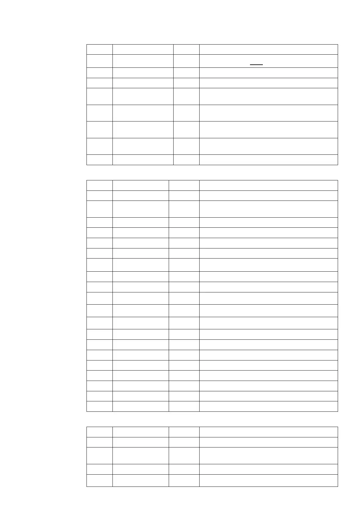
Cell Text Status Description
0205 Power Fact READ
Calculated from
Ia/–90° with respect to Vbc
0206 Frequency READ Measured frequency
0207 TapPosition READ Actual tap position
0208 Highest tap RESE
T
Highest tap used since last reset
0209 Lowest tap RESE
T
Lowest tap used since last reset
020A Total Ops RESE
T
Total number of operations
020B Freq Ops RESE
T
Total number of frequent operations
020C tREMAIN READ Time remaining to change next tap
3.3.8 Control 1
Cell Text Status Description
0300 CONTROL 1 READ
0301 CTL Links PWP Software links that are used to select the available
optional group 1control functions.
0
1 1= tINV 1 = Inverse time delay = dV.DT/(V ±Vs)
0302 CT Ratio PWP Line Current Transformer overall ratio
0303 VT Ratio PWP Line Voltage Transformer overall ratio
0304
In
PWP Rated current winding of relay (1A or 5A)
0305 Vs SET Set value of remote regulated voltage
0306 dV SET Dead band = ±dV
0307
Vc(volt/In)
SET Circulating current compensation
0308
Vr(volts/In)
SET Resistive LDC compensation
0309
Vx(volts/In)
SET Reactive LDC compensation (– = reverse)
030A pf Angle SET Low power factor LDC compensation (90°)
030B tINIT DT SET Initial definite time delay
030C tINTER SET Inter tap delay
030D tPULSE SET Tap pulse duration
030E Level 1 SET Load shedding/boosting level 1
030F Level 2 SET Load shedding/boosting level 2
0310 Level 3 SET Load shedding/boosting level 3
0311 tTapChange SET Time between tap position indications
3.3.9 Logic 1
Cell Text Status Description
0400 LOGIC 1 READ Column heading
0401 LOG Links PWP Software links that are used to select the available
optional group 1 blocking functions
1 TpFail 1 = block outside dead band for maximum time
2
Ic> blk
1 = block for excessive circulating current

 Loading...


