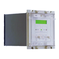
Manual
KVCG202/EN M/H
For test 3 and 6 connect L2 OPTO (terminal 50) to switch S1.
Set the load shedding/boosting setting level 1 to –3%, level 2 to –6% level 3 to –9%
[030E, 030F, 0310 CONTROL].
Apply voltage equivalent to the system voltage input setting value Vs to (terminals 17 and
18).
Close switch S1. The ‘Lower volts’ relay output contact should close.
Slowly reduce the system voltage and check the voltage at which the ‘Lower volts’ relay
output contacts re-opens. The contacts should re-open at a voltage shown in Table 5 for
test 1. Increase the system voltage to Vs the ‘Lower volts’ contacts should be closed.
Open switch S1. Repeat this for test 2 and 3 (i.e. other load shedding levels if set).
Set the load shedding/boosting setting level 1 to +3%, level 2 to +6% level 3 to +9% [Cell
Ref. 030E, 030F, 0310 CONTROL].
Close switch S1. The ‘Lower volts’ relay output contact should close.
Slowly increase the system voltage and check the voltage at which the ‘Raise volts’ relay
output contacts re-opens. The contacts should re-open at a voltage shown in Table 5 for
test 4. Decrease the system voltage to Vs the ‘Raise volts’ contacts should be closed.
Open switch S1. Repeat this for test 5 and 6 (i.e. other load shedding levels if set).
[Restore all settings changed i.e. input masks, and inter-tap delay (tINTER) setting.]
Load Shedding Setting Measured Vs
TEST L0 L1 L2
1 –3% 0 0 97% of Vs
2 0 –6% 0 94% of Vs
3 0 0 –9% 91% of Vs
4 + 3% 0 0 103% of Vs
5 0 +6% 0 106% of Vs
6 0 0 + 9% 109% of Vs
Table 5
9.6.3 Integrated timer
9.6.3.1 Initial time delay
The relay should be commissioned with the settings calculated for the application.
9.6.3.2 Definite time delay
The time delay to the first tap change initiation (initial delay) commences when the
voltage goes outside the deadband. When the voltage is within the deadband the timer
will reset at the same rate as it operates. To test the initial delay timer it is necessary to
reset the timer. This is accomplished by swinging the voltage through the deadband from
the side opposite to that which it will go to when timing is initiated.
Check that the initial time delay characteristic is set to ‘Definite’ [0301 CONTROL].
[Before making the following changes note the settings for: initial time delay (tINIT), inter
tap delay (tINTER).
Set the initial time delay (tINIT) to 30 seconds,
the inter tap time delay (tINTER) to 0 seconds.]
Set the timer to start from closing of switch S2 and stop on closing of the lower volts
contact ‘Lower volts’.
Close switch S2, adjust the applied voltage to 110% of Vs.

 Loading...