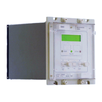
Manual
KVCG202/EN M/H
5.1.17 Total taps available (TpAvail)
The total number of taps available can be set between 1 and 40 if the VT is used for tap
position indication (TPI) or 1-30 if an external voltage is used. This setting should be set
to indicate the number of resistors used in the TPI resistor box. For example, if a resistor
box with 22 resistors is used “TapsAvail” should be set to 22, regardless of the actual
taps available on the transformer.
Two threshold settings TP> (maximum tap position) and TP< (minimum tap position) can
also be set between 1 and 40, or 1 and 30 depending on whether the VT or external
voltage is used for TPI. An alarm can be initiated if the tap position is outside the set
thresholds.
5.1.18 Tap fail time delay (tFAIL)
Alarm initiation time delay can be set between 0 and 15 minutes. An alarm is initiated if
the voltage has changed due to tap change operation in response to a valid Raise/Lower
command issued by the relay, but is unable to come within the prescribed deadband
limits within the period of preset time delay.
5.1.19 Frequent operations (Ops/TP>)(tp)
The number of taps change operations (1-100) in a given time (0-24Hrs) can be set. An
alarm is initiated if the number of tap change operations (Ops/TP> exceeds a thresholds
over a preset time (tp).
5.1.20 Power factor
The power factor angle can be set between 0 and 90 degrees. This provides
compensation for different power factors in the system where negative reactance control
is being used.
5.1.21 Tap change indication time (tTap change)
The time interval between tap changes to prevent incorrect TPI can be set to 1-3 secs.
5.2 Setting group selection
The relay has two setting groups, but as supplied only setting group 1 will be visible. To
make the second group of settings visible in the menu, set function link SD4 = 1
in the SYSTEM DATA column. The value of the group 2 settings is unimportant when
link SD4 = 0, because group 1 settings will be in use by default. The menu cell 000E, in
the SYSTEM DATA column, is a read only cell that displays the setting group that is in
operation. The logic for the setting group is given in the logic diagram in Appendix 2.
5.2.1 Remote change of setting group
Link [SD3] must be set to “1” before the relay will respond to a remote command to
change the selected setting group. Because the command cannot be sustained over the
serial link a set/reset register is used to remember the remotely selected setting group.
When link SD3 = 1, the set/reset register shall change to 0/1 in response to the
respective commands <Set Group 1>/<Set Group 2> via the serial port. When the value
of set/reset register is “0” then the group 1 settings shall be in operation and when its
value is “1” the group 2 settings will be in operation. The state of this register is stored
when the relay is powered down and restored on power up. When link SD3 = 0 the value
of the set/reset register will no longer change in response to remote commands and will
retain its last set state prior to setting SD3 = 0. When link SD3 = 0 the value of the cell
cannot be changed via the serial port and the value of this register will have no effect on
the setting group in use.
Note: that if [SD4] = 0 then the group 2 settings will be hidden and group
1 will be active by default.
5.2.2 Manual change of setting group
Link [SD4] must be set to “1” to make the second setting group active. Then manual
selection of Setting Group 2 shall be effected by setting link control link CTL2=1 in the
CONTROL column of the menu.

 Loading...