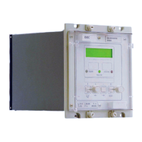
Manual
KVCG202/EN M/H
Therefore, minimum current rating = 50W and, allowing a 50% derating of the
component, a 100W resistor is required.
Therefore use RS = 0.5 Ω 100W.
Note: See short time current withstand note given in example 1.
4.7.4.2.2 Series connection of LDC circuits
As an alternative to the parallel connection of LDC circuits, the LDC circuits can be
connected in series, see Figure 29. With this series connection the LDC inputs measure
the total secondary load current derived from the parallel connection of the line CTs.
Therefore, as with the parallel connection when the number of transformers supplying the
load changes, the LDC settings on the relay will not need to be adjusted.
With this method of connection the LDC circuits measure the total load current from the
two transformers. Therefore, the VR and VXL settings can be based on rated current as
for a single transformer shown earlier. If three transformers or more are connected in
parallel then care should be taken that the LDC inputs are not thermally over rated.
The current inputs on the KVGC are rated to carry 3.2In continuously. If this is likely to
be exceeded then interposing CTs should be used to reduce the current to the LDC
inputs and the VR and VX settings should be increased accordingly.
Figure 28: Series Connection of LDC Circuits
4.7.4.2.3 Embedded generation
If embedded generation is installed close to the load centre, then this could cause
reduction or possibly reversal of real power flow through upstream transformers. The
situation with reactive power is less clear cut, depending on its type and settings, an
embedded generator may consume, generate or have zero reactive power. Therefore,
overall transformers may experience very significant changes in power factor. This is in
contrast to systems without embedded generation where the power factor is usually fairly
constant.
Changes in power factor should not cause any degradation of performance in master-
follower or circulating current schemes even if embedded generation is installed close to
the load centre and causes reversal of real and/or reactive power flow. If embedded
generation is installed on a separate line back to the substation then the current feedback
used for LDC must be arranged not to include this line.

 Loading...