MDS 05-6632A01, Rev. F MDS Orbit MCR/ECR Technical Manual 23
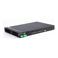
Figure 2-2. MCR Connectors and Indicators
(Sample configuration with Cell, WiFi, two Ethernet and one Serial port)
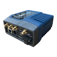
Figure 2-3 shows the unit’s front panel connectors and indicators. These items are referenced in the text
that follows. The unit’s LED Indicator Panel is described in Table 2-5.
Figure 2-3. ECR Connectors and Indicators
(Sample configuration with Cell, WiFi, Ethernet and Serial port)
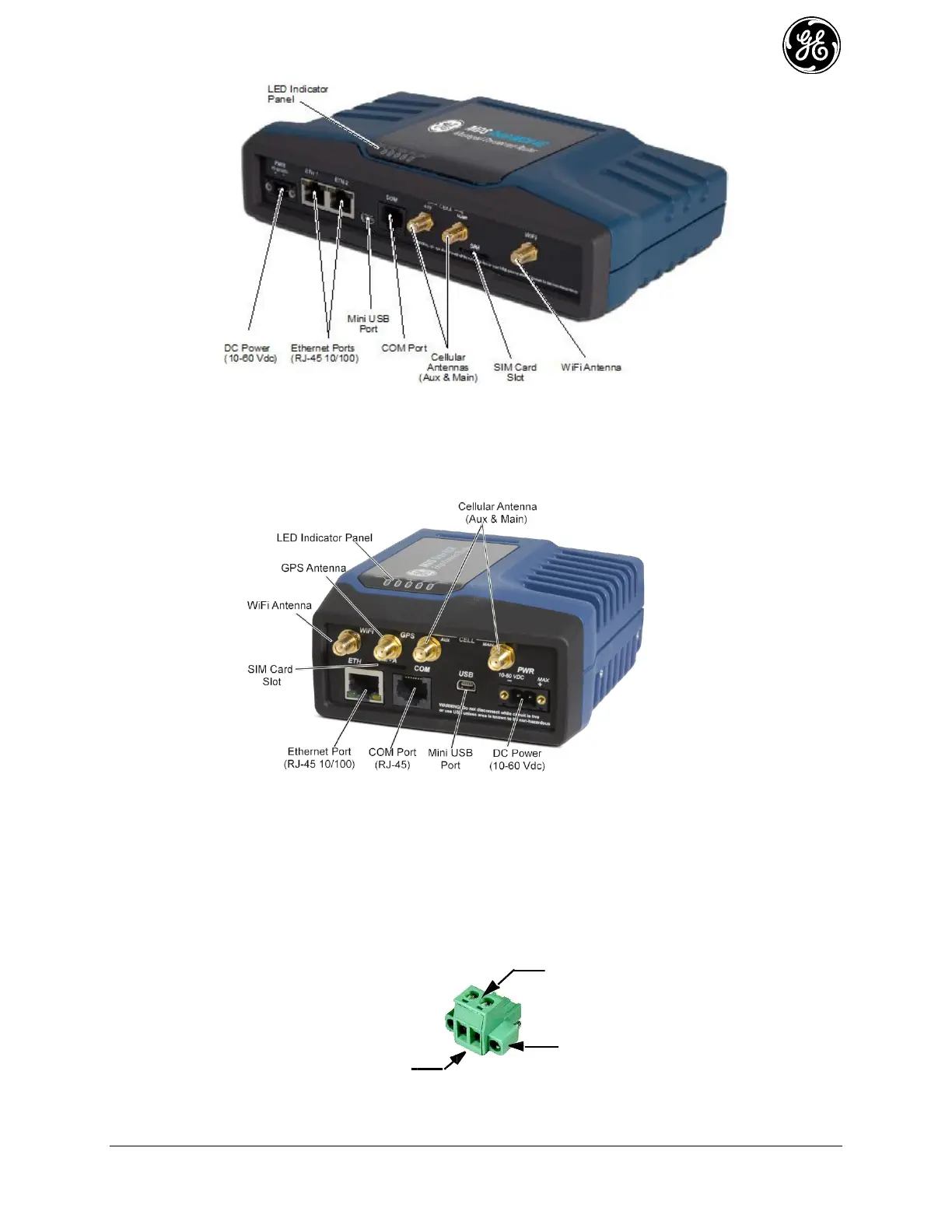
PWR—Two-conductor DC input connection .
- The DC power connector (Figure 2-4) is keyed and can only be inserted one way.
- Use Copper Conductors Only
- Use 18 AWG wire
- Tighten wire clamps to 5 lb-in. (0.6 Nm)
Figure 2-4. DC Power Connector (P/N 73-1194A39)
Lead
Screws (2)
Binding
Wire Ports (2)
(Polarity: Left +, Right –)
Retaining
Screws (2)
 Loading...