Chapter 1: Functional Description
System Functions
1-16 Service Manual
1.3.7 Service Mode
A series of restricted service menu screens allow a technician to change system defaults, perform
diagnostics and view the unit’s PCB and software revision levels. The service mode is initiated by holding
both the Help and Alarm Silence keys during power up.
1.3.8 Display
The color VGA display is driven and powered by the Control Board. The Control Board includes a dedicated
graphics controller with on-board memory. The LCD is backlit with two low voltage LED strings. The LCD
backlit driver is located on the Control Board.
1.3.9 Touch Panel
The touch panel has membrane switches and is wired to the Control Board. (Refer to Figure 1-10.) Signals
from the switches are received by the main application processor.
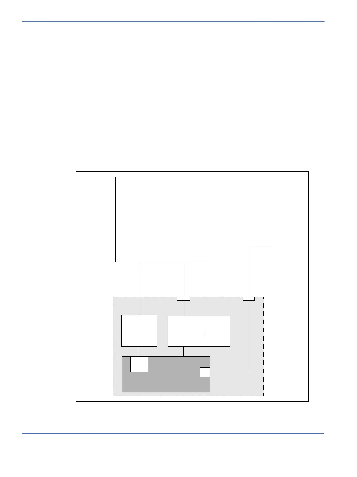
FIGURE 1-10. Touch Panel and Display
LCD Display
Touch Panel
LED Driver
Control Board
VGA
Controller
Video
RAM
PWM
IO
J5J1
Main Application
Processor
Backlight
Intensity
Control
Digital RGB
PB0 - 11
DGND