Chapter 5: Repair Procedures
Heater Housing Repairs
5-8 Service Manual
5.3.4 Power Supply Replacement (Figure 5-1)
1. Remove the upper heater housing. Refer to section 5.3.1.
2. Disconnect power supply’s electrical connectors. Disconnect wire ties from power supply mounting
plate using 2 mm hex key. Disconnect ground wire from bracket using 7 mm socket wrench. Using a
3mm hex key, remove the power supply bracket mounting screws. Remove Power Supply/Bracket
assembly and place on working surface. Remove the 4 screws using 2mm hex key and remove power
supply.
5.3.5 Alarm Light Board Replacement (Figure 5-6 and Figure 5-8)
1. Remove the upper heater housing. Refer to section 5.3.1.
2. Remove the 2 captive screws that secure the electronic enclosure on either side of the lens. Tilt the top
of the Electronics Enclosure out to allow access to the screws securing the back of the Alarm Light
Board.
3. To remove the Alarm Light Board, use a 2 mm hex key to remove the two screws that secure the Alarm
Light Board to the Electronic Enclosure. Disconnect its electrical connectors. When replacing the Alarm
Light Board, reconnect the ribbon cable first. When installed the LED’s will be oriented on the bottom of
the board.
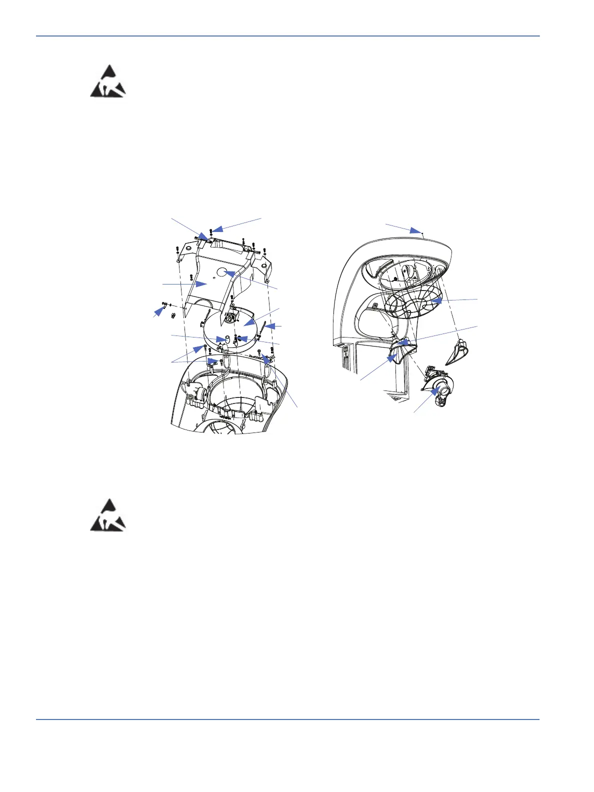
FIGURE 5-5. Heat Engine Assembly and Lights
Procedure light assembly
Observation
light tunnel
Observation
light bulb
Protective
grill
Grill mounting clip
Duct mounting screw
Thermostat
Exhaust duct
Ground wire
Laser mounting
hole
Adjustment
screws
Adjustment
screws
Ground wire
Cotter pin
Heater dish
Laser access
hole