Rack and pinion hoist
Assembly and Operating Instructions
23 / 100 BL108 GB Edition 03.2018 Rev. 02
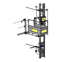
3.2.1 Operating and control elements
Main switch
On the foot section switch box
Serves the purpose of switching On/Off at the start/end of work.
In the event of malfunctions or
maintenance/repair work and at the end of
work the master switch must be secured with a
padlock to prevent it being switched on.
1 = Main switch
Manual control/ground control
The cable for the plug-in control is 5 m long.
1 = EMERGENCY STOP button
2 = UP button
3 = DOWN button
4 = Hanging bracket
If overloaded, the red warning light
(1) on the trolley switch box
illuminates.
An alarm signal also sounds.
1 = Overload control lamp
2 = Sockets for loading ramps and
limit switch