Operation
Printed in U.S.A. 103 50940411/G0219
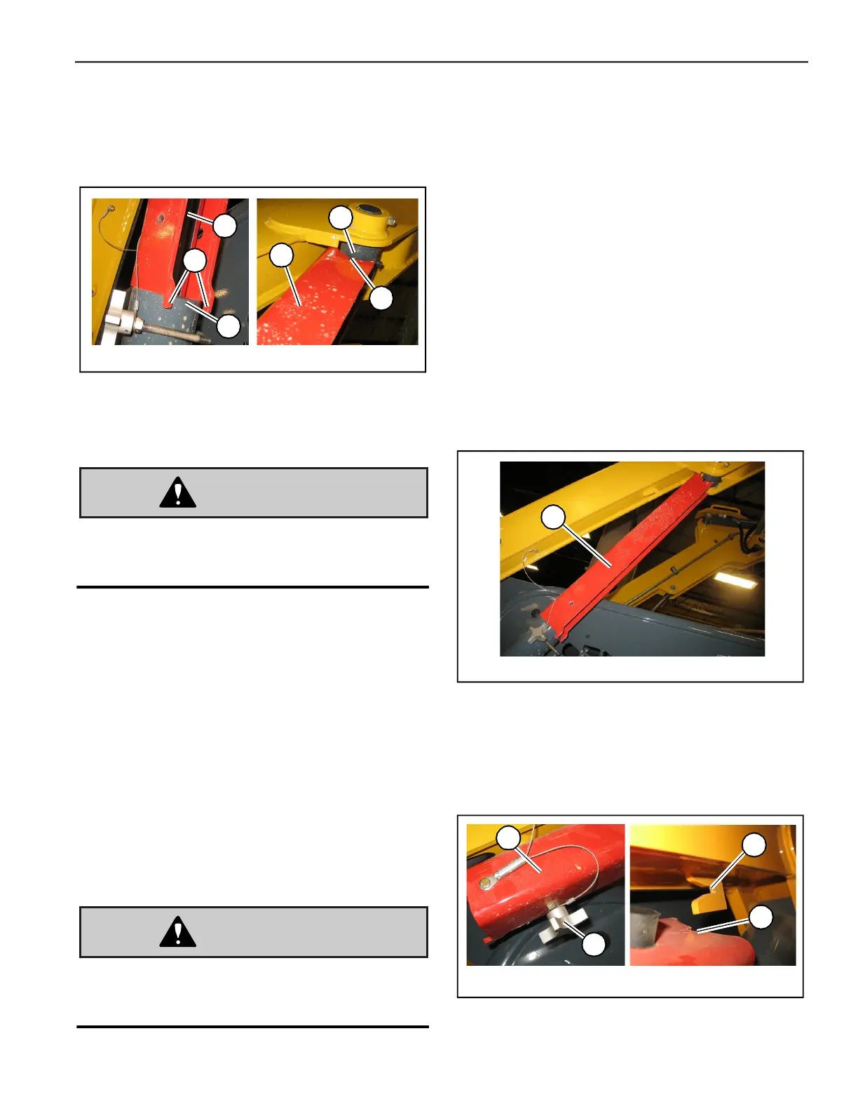
c. Position the lift arm support with the curved
end (E, Fig. 98) of the support tight against
the end of the cylinder rod (P), and tabs (T)
on the support hooked over cylinder tube
head (C) as shown.
9. Start the machine and lower the lift arm against
lift arm support (Z). Verify that lift arm support
(Z) is properly positioned as shown in Fig. 98.
The lift arm support device must be properly
positioned to prevent the lift arm from falling,
which could result in severe injury or death.
10. Shut off the engine.
11. Move the lift/tilt controls to verify that the
controls do not cause movement of the lift arm
and hitch plate.
12. Raise the safety bars/arm rests to apply the
parking brake and lock out the hydraulic
controls.
13. Unfasten the seat belt, remove the ignition key
and take it with you. Exit the machine using the
hand-holds.
Disengage Lift Arm Support
A second person on the outside of the machine
is required to assist with disengaging the lift
arm support.
1. Start the engine and raise the lift arm as high as
it will go.
2. Move the drive controls to the neutral position.
3. Shut off the engine.
4. Move the lift/tilt controls to verify that the
controls do not cause movement of the lift arm
and hitch plate.
5. Raise the safety bars/arm rests to apply the
parking brake and lock out the hydraulic
controls.
6. Stay in the machine in the operator’s position. A
second person, on the outside of the machine,
must:
a. Remove lift arm support (Z, Fig. 99) from
the cylinder rod.
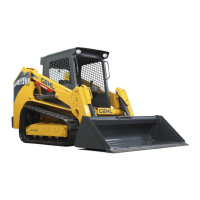
7. Securely insert notch (F, Fig. 100) on lift arm
support (Z) into retaining hook (N) on the lift
arm. Secure lift arm support (Z) in the storage
position using retaining fastener (Y). Tighten
fastener (Y) securely.
Fig. 98 – Lift Arm Support Proper Positioning
X
P
T
C
E
Z
Fig. 99 – Lift Arm Support Removal
Z
Fig. 100 – Lift Arm Support Storage Position
N
F
Y
Z