Schematics
50940411/G0219 192 Printed in U.S.A.
Model RT250 (SN 70501 and Up) Schematics
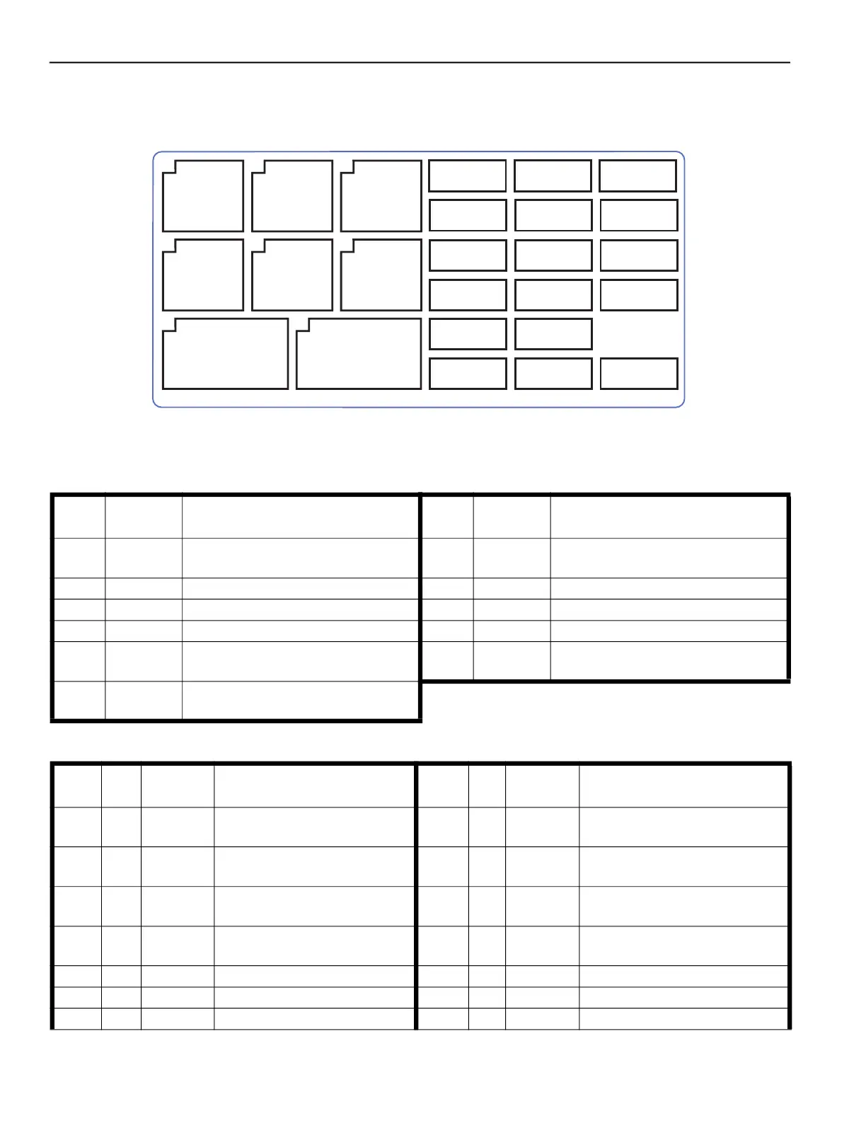
RT250 Fuse/Relay Locations Index
50311307
R7
AC Fan
R5
HVAC
R10
Wipers
R11
Park Brake
R6
Fuel Pump
F7 - 30A
Fuel Pump
F1 - 10A
Contr. #2
F14 - 10A
Door/Radio/Aux
F8 - 20A
HVAC Fan
F2 - 10A
Contr. #3
F15 - 30A
ECU
F9 - 20A
Work Lights
F3 - 20A
Contr. #1
F16 - 30A
HVAC Hi Blower
F10 - 10A
Aux Sockets
F4 - 10A
Power-A-Tach
F17 - 10A
Horn
F18 - 10A
Ignition
F11 - 20A
Wipers
F12 - 15A
Trk. Tension/
Self-Level
F6 - 10A
Disply/Joysticks
Seat/Door
R3
Horn
R8
Work
Lights
R9
Contr.
#2
F13 - 120
CAN - Bus
Ω
Fig. 179 – RT250 Relay/Fuse Box Decal
Table 58: RT250 Relays
Relay
Schematic
Page
Circuit / Notes Relay
Schematic
Page
Circuit / Notes
R1 196
Power / Relay not in fuse box; refer to
page 152
R3 200 Horn
R5 200 HVAC R6 200 Fuel Pump
R7 200 AC Condenser Fan R8 200 Front Work Lights
R9 200 Controller #2 Power R10 200 Wiper Motors
R11 200 Park Brake Switch, Power-A-Tach R12 196
Glow / Relay not in fuse box; refer to
page 152
R13 205
Power-A-Tach / Relay not in fuse box;
refer to page 152
Table 59: RT250 Fuses / Resistors
Fuse Amp
Schematic
Page
Protected Circuit / Notes Fuse Amp
Schematic
Page
Protected Circuit / Notes
Maxi 80 196
Power Relay, Ignition Switch,
Dome Light
Mega 1 100 196 Glow Relay
F1 10 199
Power Relay, Main Power,
Controller #2
F2 15 199 Controller #3 Power
F3 20 199 Controller #1 Power F4 10 199
Park Brake Light, Power-A-Tach
Switch
F5 N/A N/A N/A F6 10 199
Display, Joysticks, Seat and Door
Switches
F7 30 199 Fuel Pump, Power Splice F8 20 199 HVAC Condenser Relay
F9 20 199 Work Lights F10 10 199 Auxiliary Power Outlets
F11 20 199 Wipers F12 15 199 Track Tension, Self-Level