Operation
50940411/G0219 108 Printed in U.S.A.
If the engine should stall for any reason during
auxiliary high-flow hydraulics operation, always
turn the ignition key all the way counter-
clockwise to the “OFF” position before re-
starting the engine according to “Starting the
Engine” on page 75.
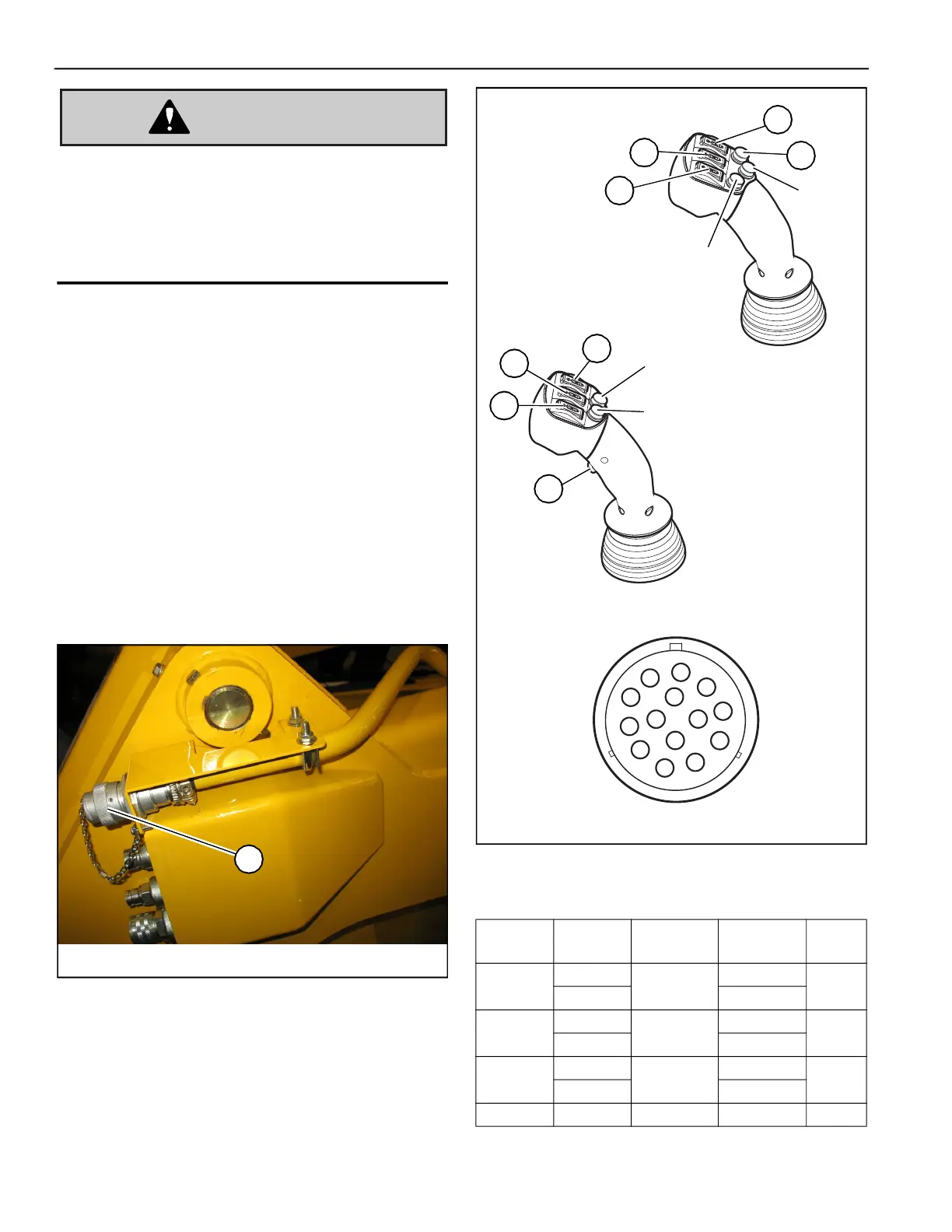
Optional 14-Pin Connector
Optional 14-pin connector (T, Fig. 108) is intended
for attachments equipped with 14-pin compliant
connections using direct 12 volt actuation control.
NOTE:
Contact your dealer for information about
approved 14-pin-equipped attachments.
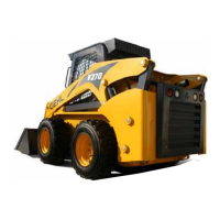
Switch / Pin Assignments
Refer to Fig. 109 and table 34 for details about
joystick switches and the associated pins in the 14-
pin connector.
Fig. 108 – Optional 14-Pin Connector
T
Table 34: 14-Pin Joystick and Pin Assignments
Joystick
Switch
Switch
Position
Switch
Type
Connector
Pin
Amp
1
Forward
Momentary
C
15
Back D
2
Forward
Momentary
E
10
Back F
3
Forward
Momentary
G
10
Back H
4 Pressed Latching A 15
1
4
2
3
Connector End View
Joystick Buttons
Horn
2-Speed
Drive
EARLY MACHINES
LATER MACHINES
1
2
3
4
Horn
2-Speed
Drive
Fig. 109 – Joystick Switch-to-Pin Assignments