Getting Started 27
5
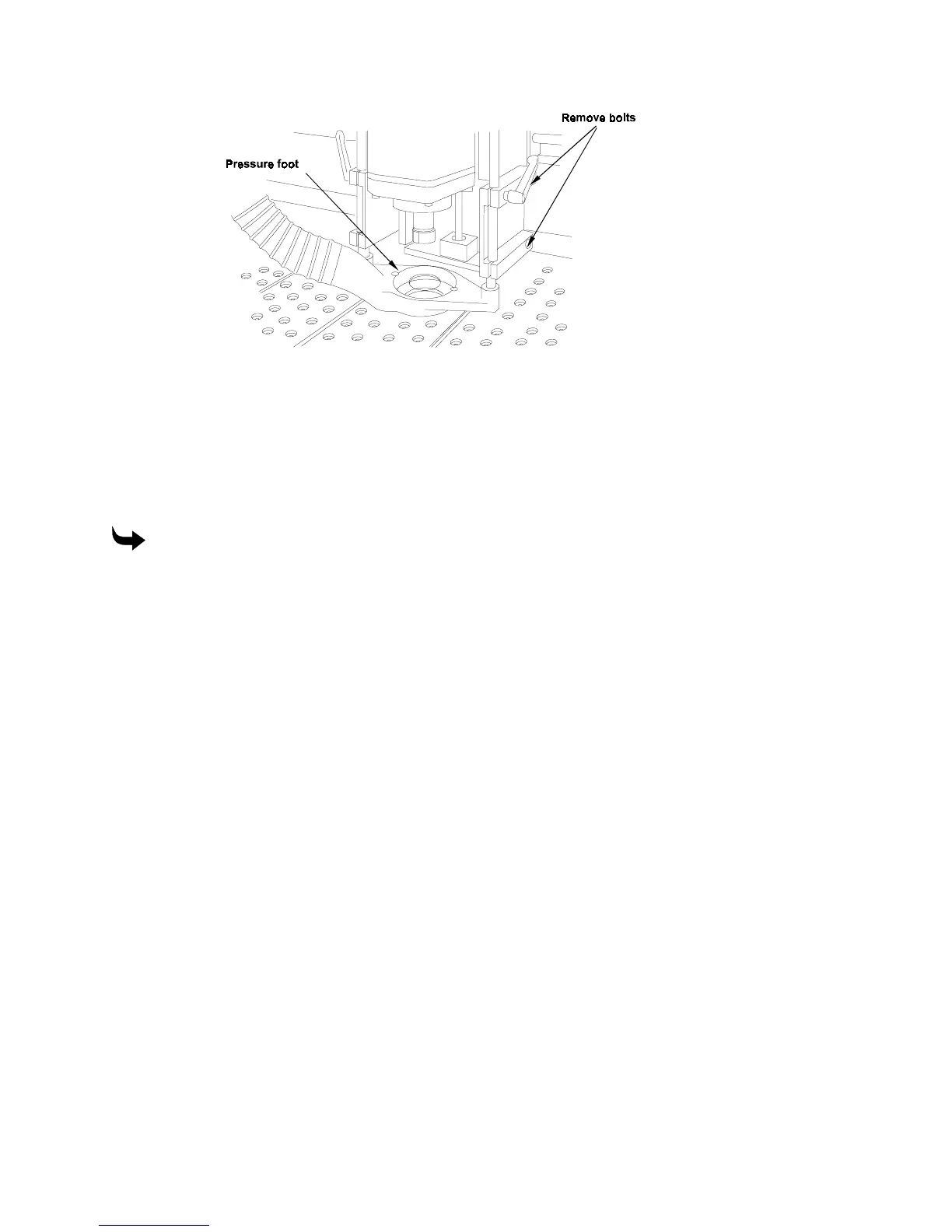
Lift off the pressure foot and vacuum shroud assembly.
Changing the pressure foot pad
The pressure foot has a removable pad that rests on the workpiece and slides smoothly over it
during cutting. The cutter extends through an opening in the pressure foot pad. Two pads are
supplied with the Sabre: a small pad with a 0.4" (10 mm) diameter opening for cutting small
pieces, and one with a 1.5" (38 mm) diameter opening for normal use.
To change the pressure foot pad
1
Raise the Z axis and the pressure foot.
2
Twist the pressure foot pad to release it from the snap fit.
3
Remove the old pad.
4
Insert a new pad.
5
Twist until the pad snaps into place.
Understanding Surface Reference
ART Path
designates a surface reference for each tool path routed by Sabre. The surface
reference point and the material thickness are used when initializing the Z axis with each tool.
The Sabre’s surface reference point changes depending on the type of tool path generated by
ART Path. ART Path generates tool paths that produce two types of results:
♦
through-cut
♦
non-through cut
Through-cut tool paths cut entirely through the material. To accurately machine a through-cut
tool path without cutting into the table, the Sabre must know the exact location of the table
surface. We call this a table surface reference. A table surface reference is used along with a
nominal material thickness because the exact thickness of the material is not required to
machine to the table. Establish a table surface reference by initializing a tool to the table using
the Z init gage.