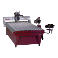
62 Sabre Owner’s Guide
~One of the axes will not
move to the Orient Point,
other axes operate
normally – NO errors
appear on Keyboard
Display.
~Problem with drive
mechanism on affected axis.
~Check for slippage in pulley-to-motor
connection; possible loose/damaged clamp
on motor pulley. Repair connection as
necessary.
PROBLEM
OCCURS
DURING
ORIENTATION
- Continued
~Check for slippage in pulley-to-Leadscrew
connection; possible loose/damaged clamp
on Leadscrew pulley. Repair connection as
necessary.
~Check for broken/damaged drive belt on
affected axis. Replace as required.
EMERGENCY
STOP
SWITCH
TESTING
~"EMGNCY SW FAULT"
lamp on Driver Board is
activated or there are
problems with shutting
down via the switches.
~"Break" in wiring cicuit for the
Emergency Stop Switches or
poor connection at the P123
position on the Tower Driver
Board.
~Activate each E-Stop Switch. If any do not
trip the Tower Circuit Breaker, concentrate
efforts on that Switch and attaching cabling.
~Check switches, cabling and harnesses for
the E-Stop Circuit. If a +24 volts dc pulse gets
to the Tower Circuit Breaker, but the Breaker
does not trip, replace the Circuit Breaker.
Cable connects Left &
Right Switches, Cable
connects Left Switch to
keyboard Support Switch,
Cable connects
Keyboard Support Switch
to Electrical Tower
connection # R166.
Check for loose connections
or damage to cabling
throughout the connecting
cabling.
~Repair / replace cabling as required.
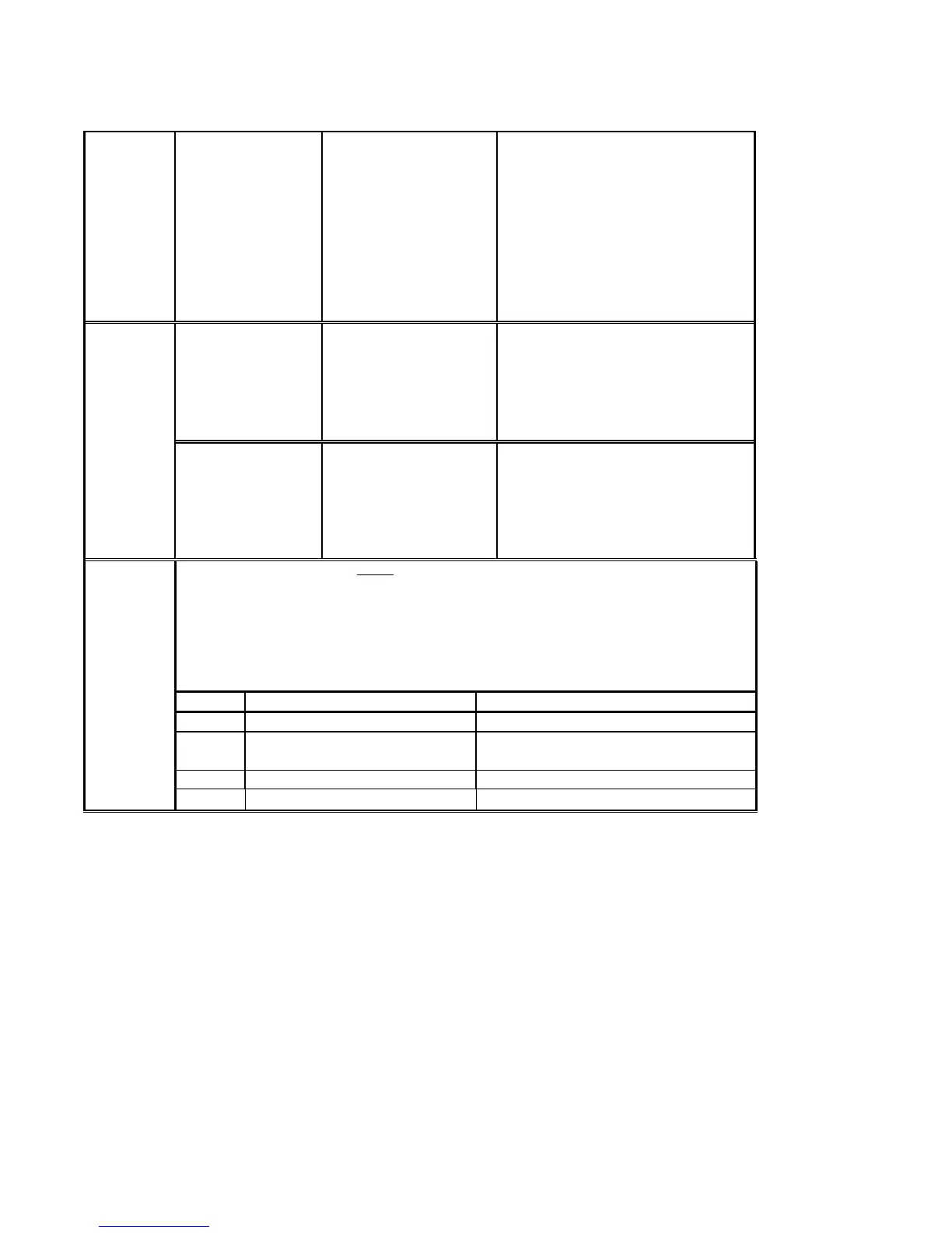
TO TEST THE
LIMIT
SWITCHES &
CIRCUITRY
The Limit Switches are normally closed. An OHM reading taken across the pins of the Limit Switch
connector usually shows between 4 and 7 OHMS. If the reading is zero or high, the Limit Switch should
be replaced. When a Limit Switch is tripped either by the Vane that the Switch straddles when the axis is
moved to the Orientation Point or by manually inserting a screwdriver, putty knife or other device that will
attract the magnets in the Switch, the OHMS should rise at a steady rate. If there is no reaction on the
Meter when the Limit Switch is tripped, replace the Limit Switch. If the Switches test out properly, repeat
the OHM test at the Tower end of the Cable Connection for the axis being tested – repair/replace as
required. If cabling tests out, check the connections of the harness for that axis where it attaches to the
Driver Board. Use the following as a reference for the Cable and harness test.
POSITION TOWER CABLE CONNECTION DRIVER BOARD
Z-AXIS UP – pins 3 & 4 / 'JUMPED' – pins 1& 2 P109 – UP – pins 1 & 2 / 'JUMPED' – pins 3 & 4
Y-AXIS REAR – pins 1 & 2 / FRONT – pins 3 & 4 P111 – REAR – pins 1 & 2 / FRONT – pins 1 &
4
*
X-AXIS RIGHT – pins 3 & 4 / LEFT – pins 1 & 2 P113 – RIGHT – pins 3 & 4 / LEFT – pins 1 & 2
*
Pin 3 is used as GND, pin 1 is common for 2 & 4