Gilson 157/159 UV-VIS Detectors User’s Guide 3-7
Operation
3
Detector Control from TRILUTION LC
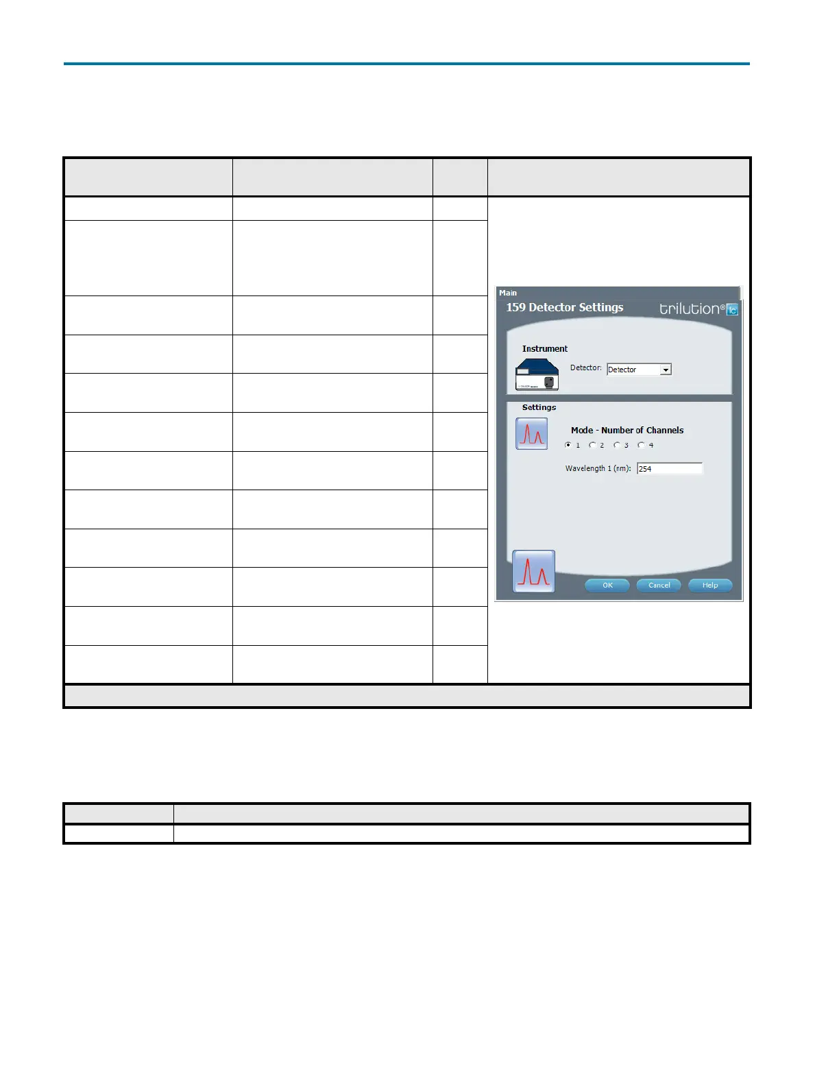
159 Detector Settings
This task sets the wavelengths for the 159 Detector.
Control - Error Handling
Optionally, use error handling to check the status of the instrument. Run a stop method to shut down the system
if an error is encountered.
159 Detector Settings
Property Name Description Default
Value
Task Property Page
Detector The detector that the task will affect. Detector
Mode Select the number of channels that will be
used to collect data. The number of
channels must match the number of
159 Detector channels set to ‘Use’ in the
configuration.
1
Mode – Number of Channels = 1
Wavelength 1
The monitor wavelength. Valid range is
190 – 750 nm.
254 nm
Mode – Number of Channels = 2
Wavelength 1
The monitor wavelength for channel 1.
Valid range is 190 – 750 nm.
254 nm
Mode – Number of Channels = 2
Wavelength 2
The monitor wavelength for channel 2.
Valid range is 190 – 750 nm.
254 nm
Mode – Number of Channels = 3
Wavelength 1
The monitor wavelength for channel 1.
Valid range is 190 – 750 nm.
254 nm
Mode – Number of Channels = 3
Wavelength 2
The monitor wavelength for channel 2.
Valid range is 190 – 750 nm.
254 nm
Mode – Number of Channels = 3
Wavelength 3
The monitor wavelength for channel 3.
Valid range is 190 – 750 nm.
254 nm
Mode – Number of Channels = 4
Wavelength 1
The monitor wavelength for channel 1.
Valid range is 190 – 750 nm.
254 nm
Mode – Number of Channels = 4
Wavelength 2
The monitor wavelength for channel 2.
Valid range is 190 – 750 nm.
254 nm
Mode – Number of Channels = 4
Wavelength 3
The monitor wavelength for channel 3.
Valid range is 190 – 750 nm.
254 nm
Mode – Number of Channels = 4
Wavelength 4
The monitor wavelength for channel 4.
Valid range is 190 – 750 nm.
254 nm
159 Detector Settings
Error Description
Instrument Error This error results when any scheduled command fails to execute or if the software loses communication with an instrument.