Configuring RF
3. Verify that the CableOS CORE GCP connection to the Pebble-2 module is working:
a. Open a ssh session directly to the CableOS Core server CLI interface using its in-band
management IP, port 22.
b. Run this command to display available Pebble-2 modules and to verify that it/they are online :
admin@CableOS> show cable rpd
Pebble-2 information is displayed:
VC:VS MAC-ADDRESS IP-ADDRESS SW-VERSION STATUS
----- -------------- ------------------- ------------------ -----------
1:10 0020.a324.14d7 192.168.8.112 6.0.20.2-1+auto29 online
Configuring RF
The RF routing configurations are installed in the RF launch amplifier and are controlled remotely via I2C
controls.
Default RF settings
The Ripple-2 node default RF settings are presented here for easy reference.
The Ripple-2 node RF tray allows full flexibility in associating the four RF ports of the node with the
downstream and upstream ports of the Pebble-2 module. The following table specifies the default
associations of RF ports which the use can re-configure using the Ripple-2 node control software.
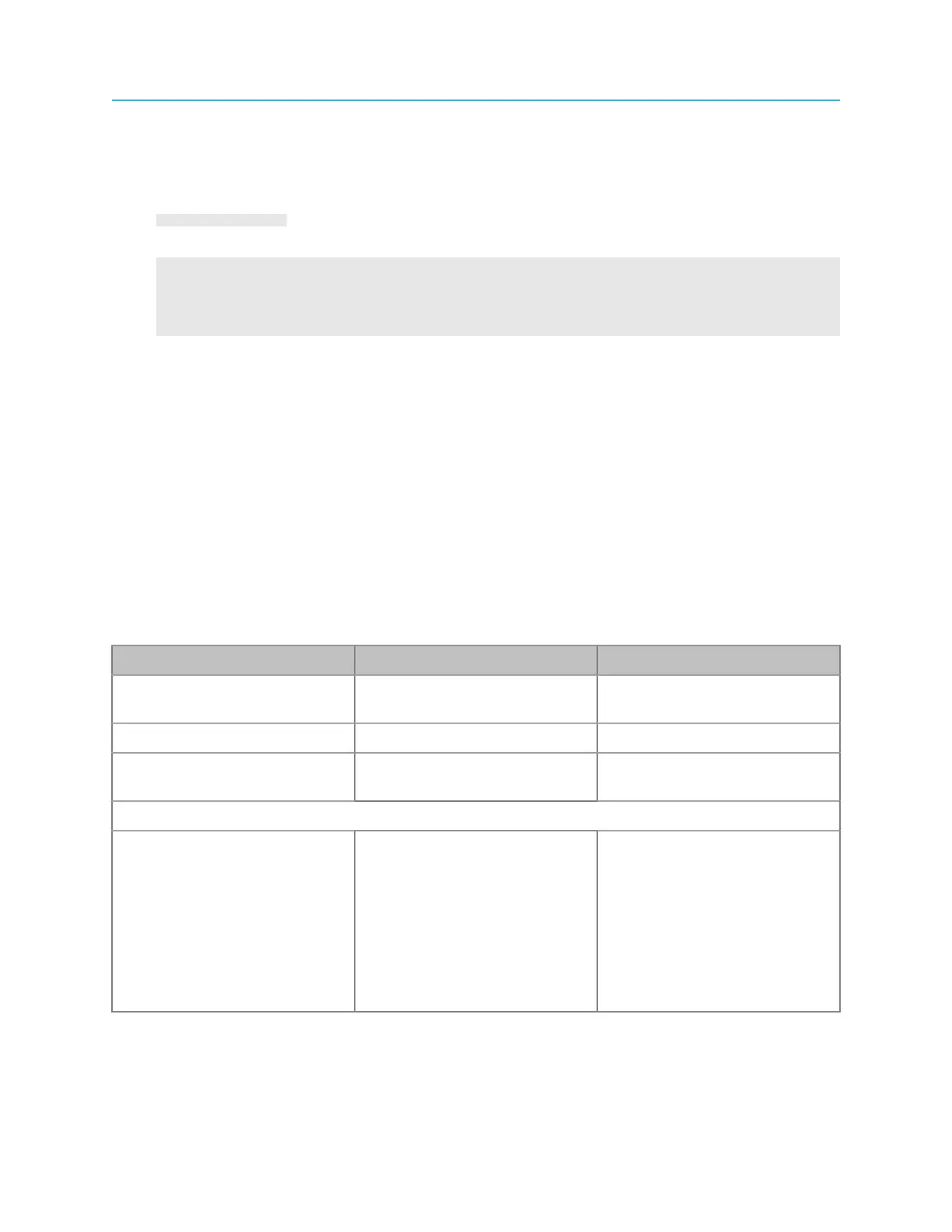
Table 5-1: Fiber node default RF settings
Item Specification Remarks
Output level 58 dBmV US channel power is set to 8
dBmV
Slope 21 dB Configurable: 10–24 dB
Attenuation 0 dB (default) Configurable: 0–31.5 dB in 0.5
dB steps
Segmentation
Pebble-2 2x4 RPD, featuring
2 DS and 4 US ports
• DS1 is routed to RF ports
P1 and P2
• DS2 is routed to RF ports
P3 and P4
• US1 is routed to P1
• US2 is routed to P2
• US3 is routed to P3
• US4 is routed to P4
Single US is always US1
(US2 not used)
59 Installation Guide