Chapter 6: Replacing field-replaceable items
2. Insert the replacement RF tray:
a. Tighten the six RF tray hold-down screws.
1. Tighten the center screws first, followed by the outer screws.
2. Tighten to 10-12 in-lbs.
b. Connect the RF tray side of the DC cable that connects to the lid motherboard.
c. Connect the RF tray side of the coax jumpers that connect to the Pebble-2 module(s).
Result: The new RF tray will be automatically initialized:
◦ The Pebble-2 detects RF tray removal/replacement.
◦ The Pebble-2 reads factory parameters from the RF tray non-volatile memory.
◦ The Pebble-2 applies specific RF tray calibration parameters: power, tilt, flatness, etc.
Related information
Tools, test equipment, and fasteners
Opening the Ripple-2 Node housing
Closing the Ripple-2 Node housing
Post maintenance testing
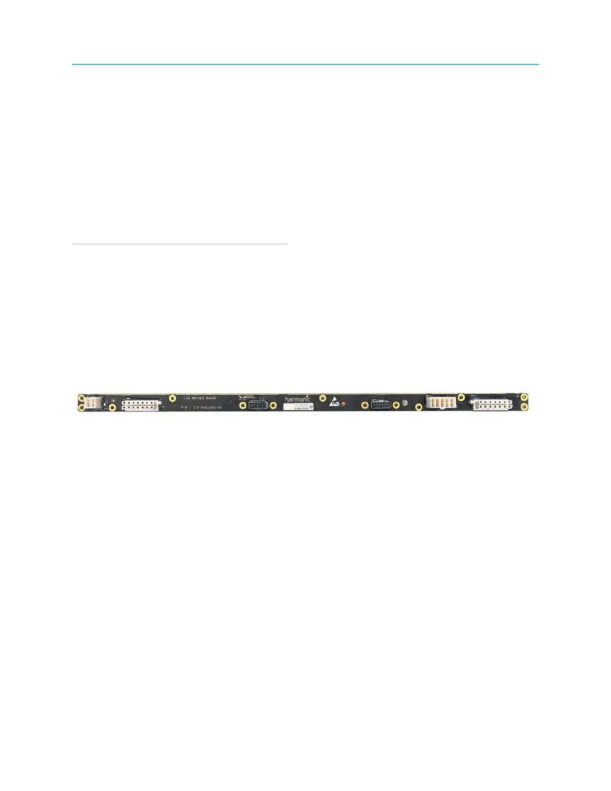
Replacing the Lid Motherboard (LMB)
Follow these steps to replace the Ripple-2 node Lid Motherboard.
Tools and materials required
• Torque wrench with 6-point 1/2" socket
• Screwdriver: Philips and medium flat-blade
• Screws, 13 (New screws must be used - (P/N 033-0885-001)
1. Disconnect the node from AC power.
2. Open the node housing.
3. Remove all modules installed on the LMB: Power supplies, Buoy, Pebble, Jetty.
4. Disconnect the AC and DC power cables from the existing LMB.
86