Chapter 4: Installing the Ripple-2 Node
Number Description
6 Lid motherboard
7 Mounting screws
8 Fiber tray
2. Use the guide pins to align the Pebble or Jetty-1 module connector with its mate connector on the lid
motherboard.
3. Firmly push the module down into the motherboard connector.
4. Secure the module with the four mounting screws using a medium flat-blade screwdriver.
5. Connect the SFP or Fin modules to the specified SFP ports and connect the fiber cables.
If you are installing the module on site as part of a new installation, continue to other installation
procedures as needed without closing the housing. For example, connect the coaxial cables and the
fiber cables, install the SFP+ transceivers and connect the fiber cables to them etc.
6. If no additional installation procedures are needed, close the node housing adhering to the Closing the
Ripple-2 node housing procedure.
7. If power to the node was previously disconnected, restore the power.
Connecting fiber cables to the Ripple-2 Node
The fiber cables are inserted into the Ripple-2 node through either one of the two optical inputs located on
either side of the node lid. Pebble-2 and Jetty-1 modules should be installed before connecting the fiber
cables.
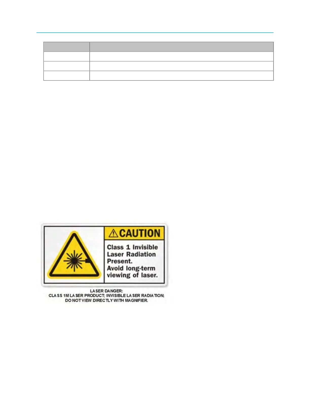
Viewing the laser output with optical instruments, such as a magnifier or microscope, within a
distance of 100 millimeters (four inches) may pose an eye hazard.
The fiber-cable installation procedure here is a generic presentation. The actual field deployment may
vary slightly with the type of cable you are using. Be sure to follow the manufacturer's instructions for the
SFP modules being used in the Ripple module. Use only SFP+ devices classified Class 1 Laser.
In addition, take proper precautions for the care and cleaning of the fiber cables' optical components.
42