Powering the Ripple-2 Node
5. Ré-installation du support RF:
a. Resserrez les six vis de retenue du support RF.
1. Commencez par les vis centrales, puis poursuivez avec les vis extérieures.
2. Appliquez un couple de serrage de 13,5-16 Nm.
b. Reconnectez le côté support RF du câble CC raccordé à la carte mère du couvercle.
c. Reconnectez le côté support RF des cavaliers coaxiaux raccordés au(x) module(s) Pebble-2).
Routing power through the Ripple-2 node
The 30A fuse array on the AC board port fuse sockets determines how AC power from an external power
source can be connected to the Ripple-2 node, sets the power distribution within the node and sets power
channeling out of the node through other RF ports to other nodes in a cascaded array. The fuse array,
together with the internal power-supply configuration and the connection to the external power grid, also
sets power high availability (HA).
Up to four 30A fuses, which are shipped with the Ripple-2 node and taped to the fiber tray in the lid, can
be installed according to the power configuration you choose. The examples below illustrate various
power configuration and routing options and the results of each are listed after each example. Use the
examples to configure other variations of power routing according to your requirements.
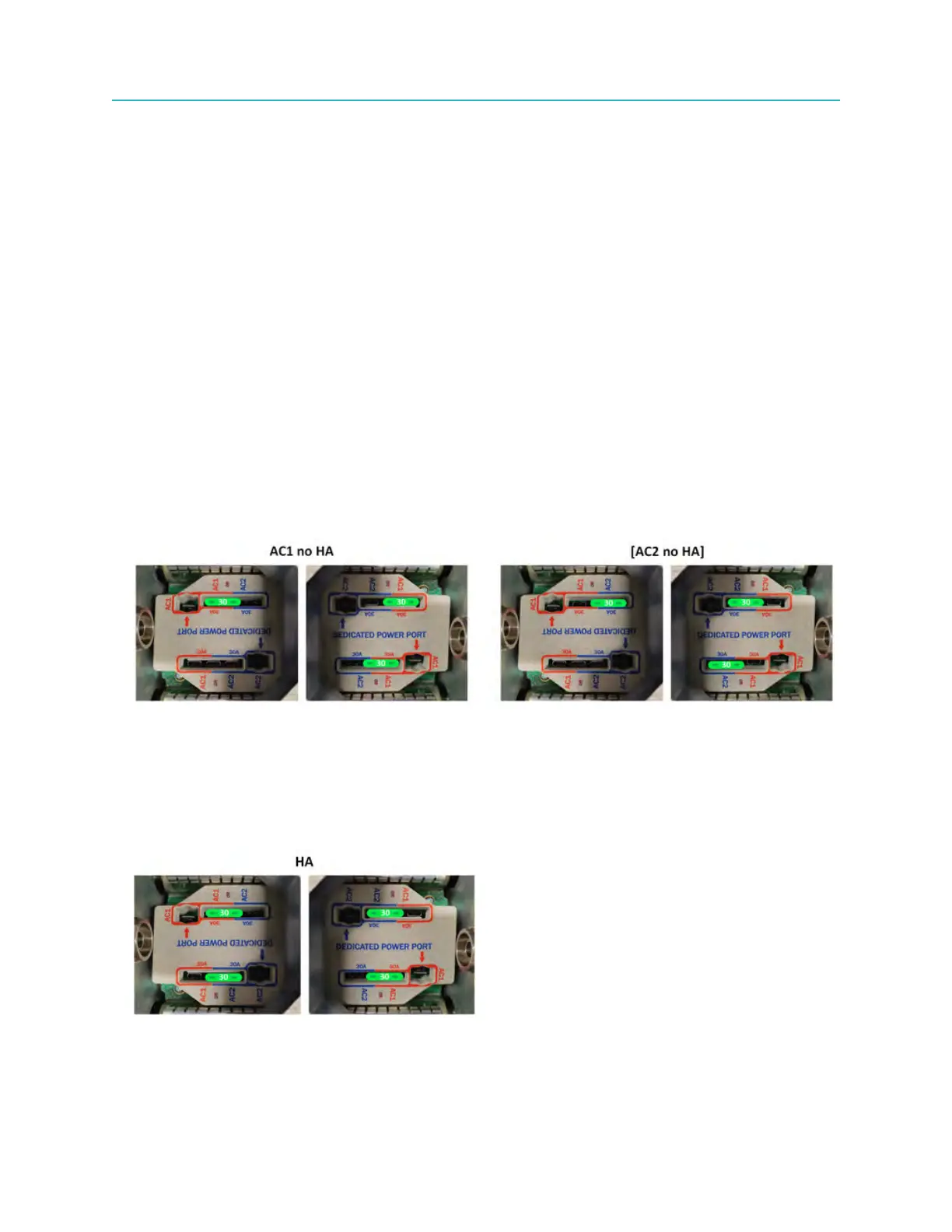
Set up the power configuration using the following examples as a guide.
• Power from external AC power source connected to P1 is channeled by P1/AC1 [P1/AC2] fuse to AC1
[AC2] internal power supply.
• Power channeled through P3 and P4 AC1 [AC2] fuses out of node to other target nodes in cascade.
• P2 is not powered and only passes RF.
• No high availability (redundancy capability) for outside power source.
• No high availability for internal power supply.
79 Installation Guide