Chapter 6: Replacing field-replaceable items
NOTE: The voltage of the line power supply must be in the range of 45-95VAC QSW. Specifically,
either 60VAC QSW or 90VAC QSW power supplies are suitable.
Tools
• Torque wrench with 6-point 1/2" socket
• Medium flat-blade screwdriver
1. Detach all the node lid bolts with the torque wrench and open the lid to expose the module slots.
2. Hold the Skiff temporary power supply by its handle and carefully insert its lower edge (facing exterior
edge of the lid) under the fiber channel, aligning the power supply module connectors with their mate
connectors on the lid motherboard.
3. Push the module firmly down into the lid motherboard connectors.
4. Secure the power supply module with the four mounting screws using a medium flat-blade
screwdriver.
When wet and/or rainy conditions are expected, the field technician should perform the following steps
in order to keep the node housing closed during node servicing:
a. Disconnect the F-type connector on the RG59 coaxial cable from the right angled F-type AC
adapter on the Skiff.
b. Feed the RG59 coaxial cable from outside into the node through either one of the node’s two fiber
ports.
c. Reattach the F-type AC adapter on the RG59 coaxial cable to the right angled F-type AC adapter
on the Skiff.
d. Mount the grommet on the RG59 coaxial cable to the fiber port on the node housing.
5. Close the node housing, strictly adhering to the Closing the Ripple-2 Node housing procedure.
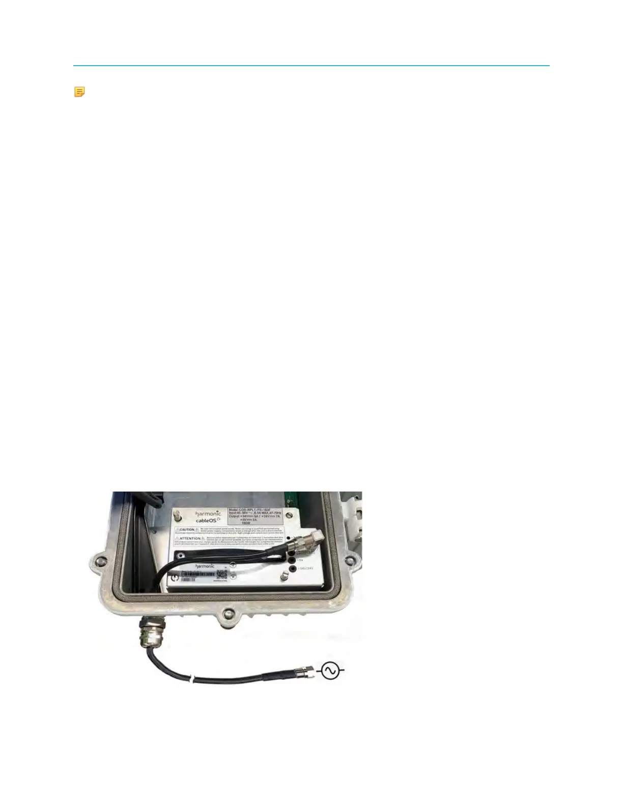
The following picture shows the Skiff power supply installed in the right power supply slot (slot 2) of the
Ripple node housing with the grommet on the RG-59 coaxial cable mounted to the fiber port.
92