Chapter 1 Introduction Mechanical Structure
© 2013 Harmonic Inc. Harmonic All rights reserved. 20 Ellipse 3000 Release 3.0, Rev. B
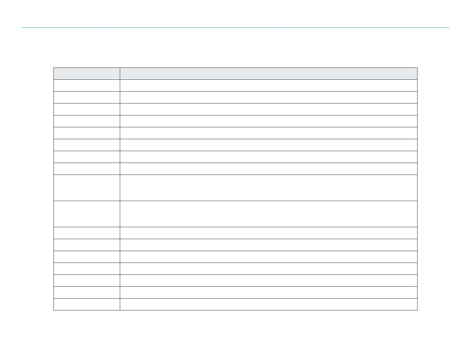
Table 1–2 describes the connectors on the rear panel
Table 1–2: Ellipse 3200 Rear Panel Connectors
Connector Description
SDI IN 1x SMPTE 259M Serial Digital Interface (SDI) input, MPEG-2/H.264 streams
CV IN 1x Composite Video (CV) input
SDI OUT 1x SMPT 259M SDI loop through output, video input feed streams
SYNC LOCK IN, OUT Front end synchronization clock. IN: for external clock, OUT: for loop through
AES/EBU1–4 4x IEC 60958 AES/EBU 1–4 audio inputs
ANLG L,R 2x Pairs of analog left/right stereo inputs
ASI IN1 1x DVB-ASI input interface
ASI OUT1 1x DVB-ASI output interface
IF/Out, Mon IF Modulator version:
■ 1x IF Level Modulated connector for IF-level output
■ 1x L-Band Monitoring connector for L-Band monitoring signal
L-Band/Out, Mon L-Band Modulator version:
■ 1x L-Band Output connector for L-band modulated.
■ 1x L-Band Monitoring connector for L-Band monitoring signal.
10 MHz Ref. CLK L-Band Modulator version:1x 10 MHz reference clock for the next uplink stage (SHF converters and amplifiers)
DVB o IP 1,2 2x GbE IP interfaces
MNG 1x RS-232 serial connector for management
DATA 1x Serial connector for MPE interface
MONITOR 1x External console interface (RS-232) for control and monitoring. For advanced users and/or Harmonic technical support personnel.
LSD 1x Low Speed Data (LSD) interface
GPI/O 1x General Purpose Interface configurable Output (GPI/O) dual dry connectors for alarms
 Loading...
