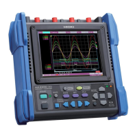
13.1 MR8880-20 Specifications
233
Chapter 13 Specifications
13
(8) Trigger Function
Trigger method Digital comparison
Repeat recording Single, Repeat
Trigger timing
• High-speed function: Start
• Real-time function: Start, stop, start&stop (conditions can be set
for each of start and stop)
Trigger criteria AND or OR possible between all trigger sources
Trigger source
Trigger source selectable for each channel
Free-running when all trigger sources are Off
1. Analog inputs: CH1 to CH4
2. Logic inputs: LA1 to LA4, LB1 to LB4 (4 channels x 2 probes)
3. External trigger: Input signal to external trigger terminal
Interval trigger
Fixed interval recording at specified measurement interval (day,
hour, minute, second) is possible.
A trigger is applied simultaneously with start of measurement, and
then a trigger is subsequently applied at the set measurement
interval. (Use the schedule function to specify the start time.)
Trigger types
(analog)
1. Level trigger
A trigger is applied when rise or fall to set voltage value.
2. Window trigger
Set the upper and lower limits of trigger level
3. Voltage drop trigger ([Highspeed] only)
A trigger is applied when the voltage peak falls below the set
level.
(Dedicated for commercial power supply of 50/60 Hz.
The trigger can not be set with the time base range of 50 ms/div
and 100 ms/div.)
4. Waveform judgment trigger ([Highspeed] only)
A trigger for performing waveform judgment in real time.
(Dedicated for commercial power supply. The trigger can not be
set with the time base range of 50 ms/div and 100 ms/div.)
Comparison targets: Sine wave and previous waveform
Judgment period: 20 µs (with 100 μs to 2 ms/div), sampling
period (with 5 ms to 20 ms/div)
Maximum sampling speed: 1 MS/s (with time base of 100 µs/
div)
Trigger types (logic)
Pattern trigger: Settable to 1/0/x for each input (ignore x)
• Configure the pattern setting for each probe.
• The trigger condition (AND/OR) can be set between logic input
channels in each probe.
• The trigger condition between probes is in accordance with over-
all trigger condition (AND/OR).

 Loading...