3.7 Connecting the Current Sensors
32
The CT7642, CT7742, CT7044, CT7045, and CT7046 Current Sensors can be used to measure large
currents of 1000 A and greater. When using these current sensors, connect them to the instrument via
the CT9920 Conversion Cable.
When connecting a sensor via the CT9920 Conversion Cable, it is necessary to configure a setting to
select the current sensor being used.
See "3.10 Setting the Current Sensors" (p. 38)
Use an external VT (PT) or CT. By specifying the VT or CT winding ratio on the instrument, the input level
at the primary side can be read directly.
See "4.2.6 Setting Scaling (when using VT(PT) or CT)" (p. 61)
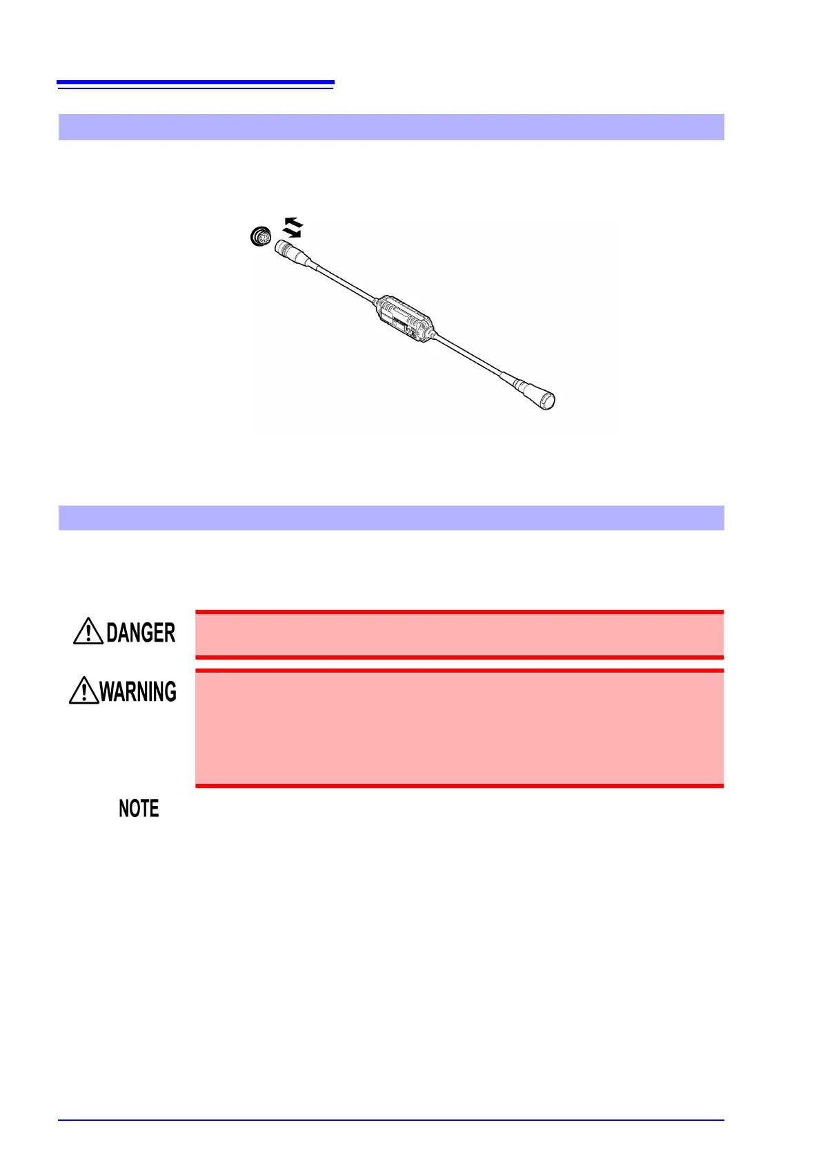
Connecting the CT7000 series sensors
CT9920 Conversion Cable
PW3390 side
Current sensor side
To measure voltage and current beyond the range of the instrument or current sensor
During wiring, avoid touching the VT (PT), CT or input terminals. Exposed live con-
tacts can cause electric shock or other accident resulting in personal injury or death.
• When using an external VT (PT), avoid short-circuiting the secondary winding.
If voltage is applied to the primary when the secondary is shorted, high current
flow in the secondary could burn it out and cause a fire.
• When using an external CT, avoid open-circuiting the secondary winding. If
current flows through the primary when the secondary is open, high voltage
across the secondary could present a dangerous hazard.
• Phase difference in an external VT (PT) or CT can cause power measurement
errors. For optimum power measurement accuracy, use a VT (PT) or CT that exhib-
its minimal phase difference at the operating frequency.
• To ensure safety when using a VT (PT) or CT, one side of the secondary should be
grounded.
 Loading...


