9.3 Connecting
99
9
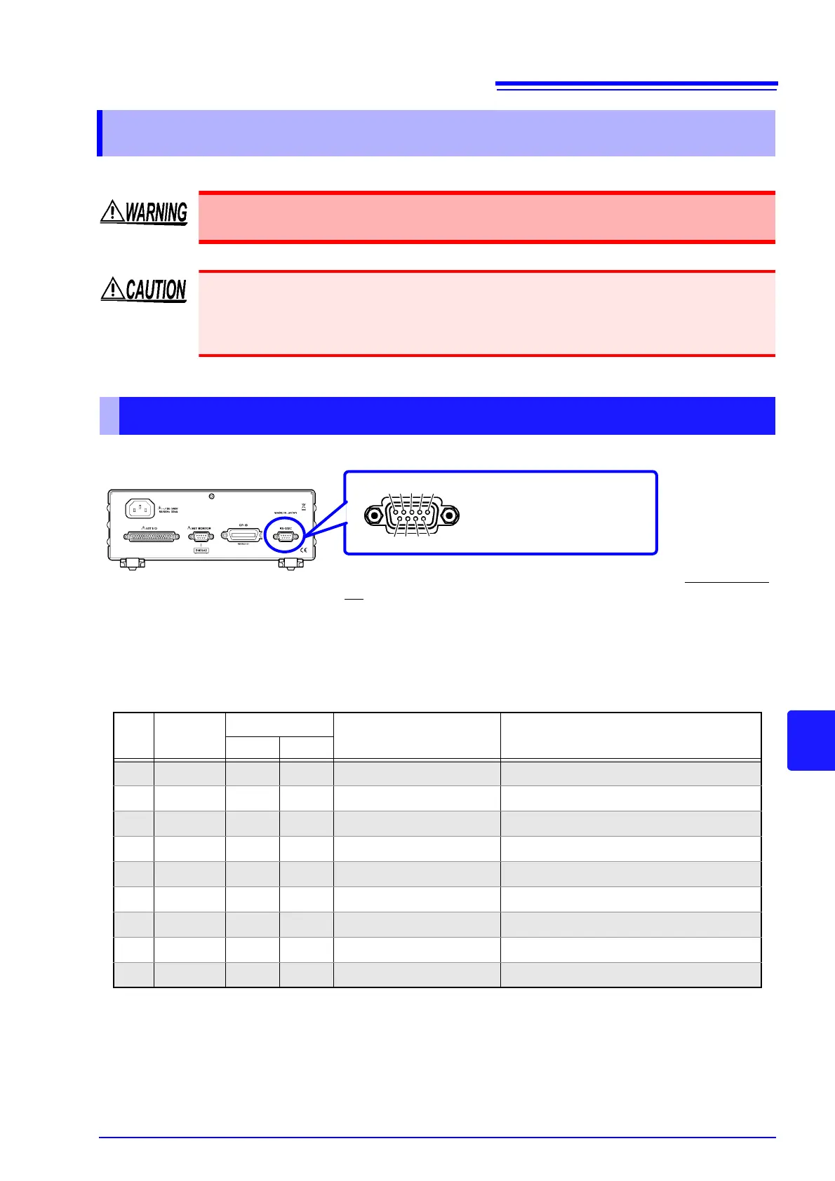
Connect the RS-232C cable to the RS-232C connector.
9.3 Connecting
Always turn both devices OFF when connecting and disconnecting an interface con-
nector. Otherwise, an electric shock accident may occur.
• To avoid damage to the instrument, do not short-circuit the terminal and do not input volt-
age to the terminal.
• If the connectors are not securely mated, operation may fail to meet specifications, and
damage could result.
Using the RS-232C Interface
Pin No
Signal
Name
Code Addr.
Mutual connection
circuit name
Remarks
EIA JIS
1 DCD CF CD Carrier Detect Not used
2 RxD BB RD Receive Data
3 TxD BA SD Transmit Data
4 DTR CD ER Data Terminal Ready Active (ON) level is +5 to +9 V (constant)
5 GND AB SG Signal Ground
6 DSR CC DR Data Set Ready Not used
7 RTS CA RS Request to Send Active (ON) level is +5 to +9 V (constant)
8 CTS CB CS Clear to Send Not used
9 RI CE CI Ring Indicator Not used
Male 9-pin D-sub
#4-40 attaching screws
To connect the instrument to a controller (DTE), use a crossover ca-
ble compatible with the connectors on both the instrument and the
controller.
The I/O connector is a DTE (Data Terminal Equipment) configuration.
This instrument uses only pins 2, 3, and 5. The other pins are uncon-
nected.
6 7 8 9
1 2 3 4 5
Rear Panel