8.1 External Input/Output Connector and Signals
85
8
The EXT I/O connector on the rear of the instrument supports external control by providing output of
the end-of-measurement and comparator decision signals, and accepting input of measurement
trigger and key-lock signals. All signals are isolated by optocouplers (inputs and outputs share a
common signal ground).
Confirm input and output ratings, understand the safety precautions for connecting a control sys-
tem, and use accordingly.
External Control Chapter 8
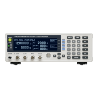
Signal input/output
Connect the instrument’s EXT I/O
connector to the signal output or
input device.
Make instrument settings
(p. 93)
8.1 External Input/Output Connector
and Signals
To avoid electric shock or damage to the equipment, always observe the following
precautions when connecting to the EXT I/O terminals.
• Always turn off the power to the instrument and to any devices to be connected
before making connections.
• During operation, a wire becoming dislocated and contacting another conductive
object can be serious hazard. Make sure that connections are secure and use
screws to secure the external connectors.
• Ensure that devices and systems to be connected to the EXT I/O terminals are prop-
erly isolated.
To avoid damage to the instrument, observe the following cautions:
• Do not apply voltage or current to the EXT I/O terminals that exceeds their ratings.
• When driving relays, be sure to install diodes to absorb counter-electromotive force.
•
Be careful not to short-circuit ISO_5V to ISO_COM.
See: "Connector Type and Signal Pinouts" (p. 86)