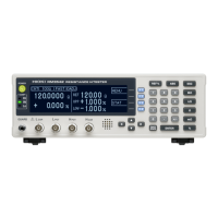
Resistance Measurement
The factory defaults (initial settings)
are optimized for chip-component
resistance measurements. The
RM3542 can also measure devices
that are otherwise difficult to mea-
sure with high current, such as fer-
rite-bead and small multilayer
inductors (low-power resistance
measurement, p. 28).
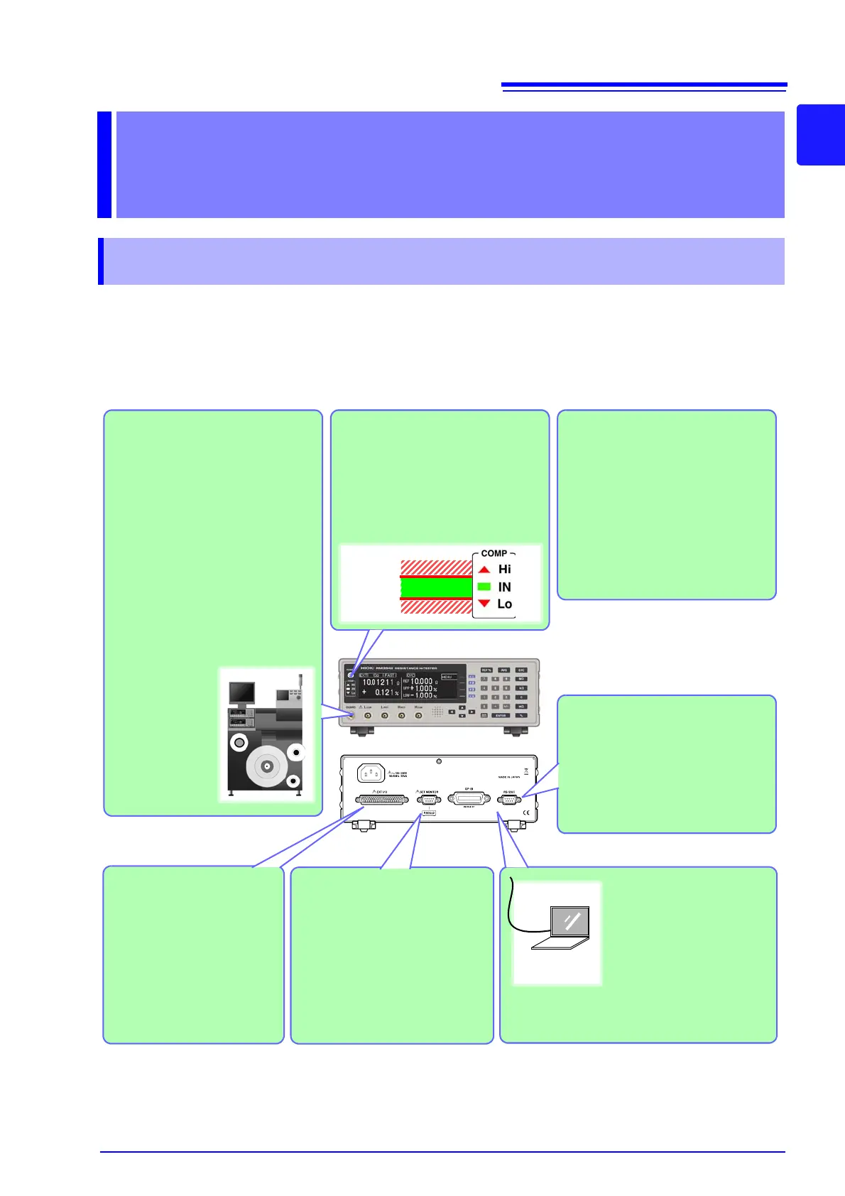
Interface
Communications
Connect the instrument to a
controller via the RS-232C
or GP-IB interface to control
measurement data acquisi-
tion (p. 97).
Send Measurement Data and
Calculation Results to a
Printer
Use a commercially available print-
er with a serial interface to print
measured values and calculation
results (p. 79).
Save and Output Measured
Values
Measured values can be stored in
internal memory (p. 69)
Statistical calculations can be per-
formed on the stored data, which
can be transferred to a computer in
batch form (however, stored data
cannot be confirmed internally).
Judge Measured Values
Measured values are compared
with a pre-specified reference value
or thresholds, and the result is out-
put externally and indicated by the
COMP indicators (comparator func-
tion, p. 34).
Connect a PLC or
I/O Board
To control from a PLC, con-
nect to the EXT I/O connec-
tor. In addition to comparator
results, various measurement
anomaly signals can be out-
put (p. 85).
Upper limit
Lower limit
Compare Two Instrument’s
Setting Conditions
When measuring with two inter-
connected instruments, settings
are compared, and an alarm is
output and measurement is inhib-
ited if the settings differ (Settings
Monitor function, p. 53).
Optional Hioki probes and fixtures
are available to connect to the mea-
surement jacks (BNC jacks, p. 4).
Alternatively,
commercially
available cables
such as 1.5D-2V
coax can be used
(p. 24).