1.1 Product Overview and Features
14
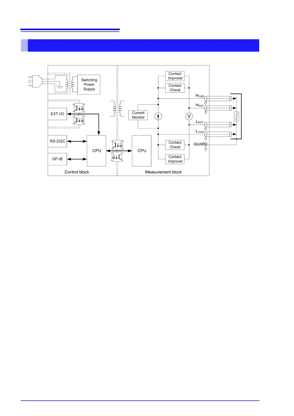
• Constant current (determined by the measurement range) is applied between the H
CUR
and L
CUR
terminals while volt-
age is measured between the H
POT
and L
POT
terminals. The resistance value is obtained by dividing the measured
voltage (B) by the constant current flow (A).
• The effects of large offset voltage such as from thermal emf are reduced by current flowing in the positive and negative
directions (A).
• The constant current source (A) and voltmeter (B) circuit designs are largely unaffected by contact resistance.
• Faulty measurement values caused by unstable or chattering contact conditions can be eliminated by monitoring (C)
the detection voltage (B) waveform (Voltage Level Monitor function).
• Stable measurements are ensured by providing sufficient integration time (the default setting is 0.3 ms). (The integra-
tion time can be reduced to 0.1 ms to support even higher speed (B).)
• Before measuring, the Contact Improver circuit (D) optimizes contact when the probes touch the DUT.
• By also performing contact checking (E), short circuits between CUR and POT terminals caused by a clogged probe tip
can be detected (probe short-circuit detection function).
• When measurement starts, the contact check circuit (E) and constant current monitor (F) are activated to monitor for
fault conditions while measuring. The dual-CPU (C and G) design provides ultra-high-speed measurements and fast
system response.
• Immunity from electrical noise is provided by isolation between the Measurement and Control blocks (H).
• The auto-ranging 100-to-240 V switching power supply (I) can provide stable measurements even in poor power quality
environments.
Block Diagram