Appendix 3 Unstable Measurement Values
A4
(3) Multi-Point Contacts with Clip Leads
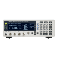
The ideal conditions for four-terminal measurements are
shown in Fig. 4: current flows from the far probe and voltage is
detected with uniform current distribution.
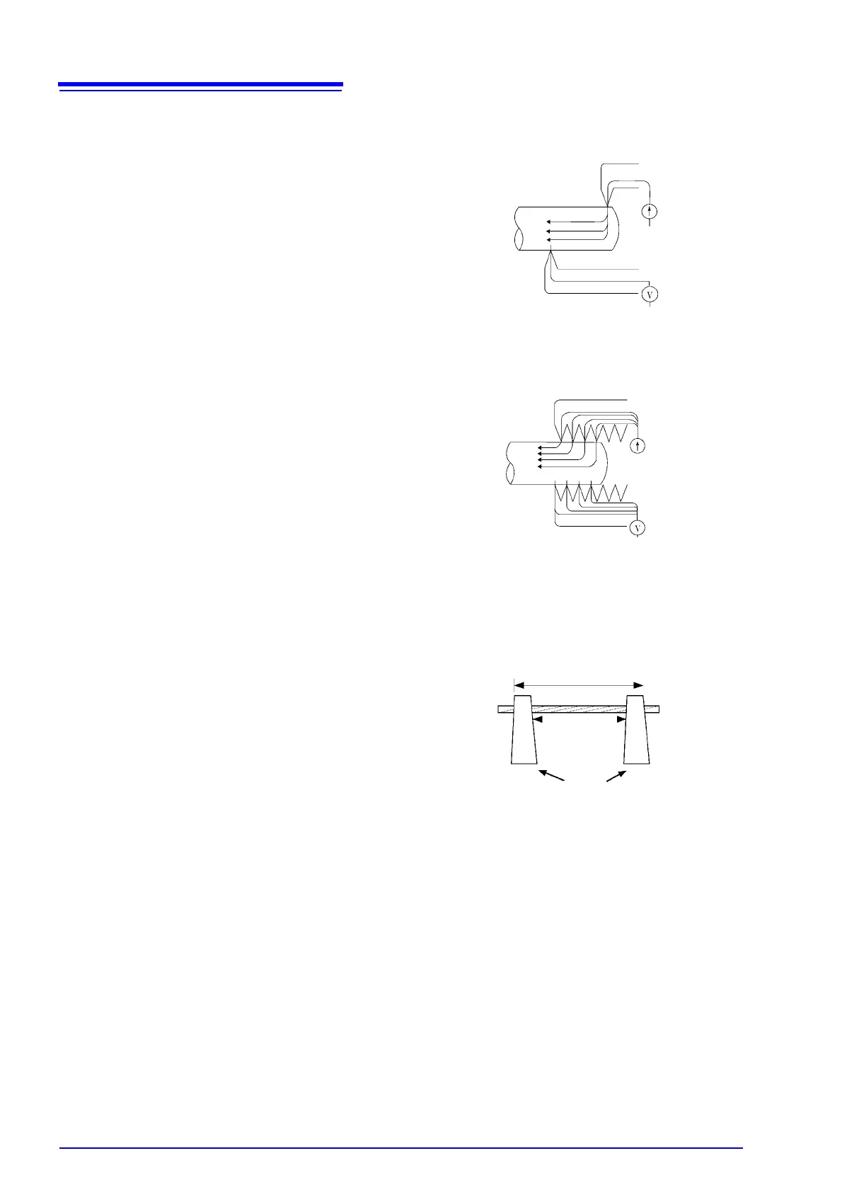
To facilitate measurement, the tips of the Model 9140 4-Termi-
nal Probe are jagged.
When a clip is opened as shown in Fig. 5, measurement cur-
rent flows from multiple points, and voltage is detected at multi-
ple points. In such cases, the measurement value varies
according to the total contact area.
Additionally, as shown in Fig. 6, when measuring the resis-
tance of a 100 mm length of wire, the length between the near-
est edges of the clips is 100mm, but the length between the
farthest edges of the clips is 110mm, so the actual measure-
ment length (and value) has an uncertainty of 10mm (10%).
If measured values are unstable for any of these reasons, max-
imize stability by measuring with point contacts as far as possi-
ble.
Figure 4. Ideal Four-Terminal Method
H
POT
, (L
POT
)
(Voltage Detection)
H
CUR
, (L
CUR
) (Current Source)
Figure 5. Measurement with
Model 9140 4-Terminal Probe
H
POT
, (L
POT
)
(Voltage Detection)
H
CUR
, (L
CUR
) (Current Source)
Figure 6. Measuring the resistance of
a 100 mm length of wire
Clips
110 mm
100 mm