if the coolant temperature warning light does not come on when the temperature is high
(more than 117 ~ 123 °C (242.6 ~ 253.4 °F):
(1). Connection reliability
Check whether the wire connected to the
sensor is strong
CONTINUITY
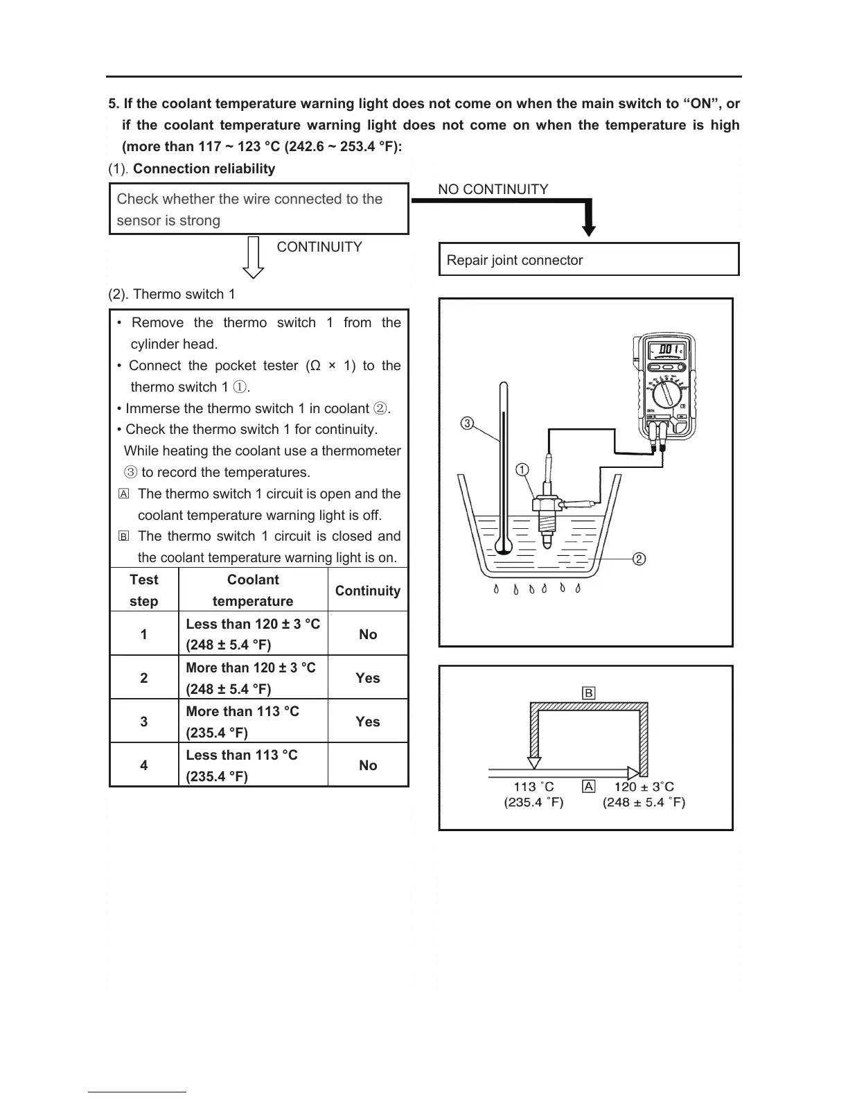
(2). Thermo switch 1
• Remove the thermo switch 1 from the
cylinder head.
• Connect the pocket tester (Ω × 1) to the
thermo switch 1 ①.
• Immerse the thermo switch 1 in coolant ②.
• Check the thermo switch 1 for continuity.
While heating the coolant use a thermometer
③ to record the temperatures.
□
A
The thermo switch 1 circuit is open and the
coolant temperature warning light is off.
□
B
The thermo switch 1 circuit is closed and
the coolant temperature warning light is on.
Test
step
Coolant
temperature
Continuity
1
Less than 120 ± 3 °C
(248 ± 5.4 °F)
No
2
More than 120 ± 3 °C
(248 ± 5.4 °F)
Yes
3
More than 113 °C
(235.4 °F)
Yes
4
Less than 113 °C
(235.4 °F)
No
ELECTRICAL COMPONENTS
- 259 -
Test steps 1 & 2: Heating phase
Test steps 3 & 4: Cooling phase
WARNING:
Handle the thermo switch 1 with special
care.
Never subject it to a strong shock or allow
it to be dropped. Should it be dropped, it
must be replaced.
COOLING SYSTEM
CIRCUIT DIAGRAM(
See 296 page)
BAD CONDITION
Replace the thermo switch 1