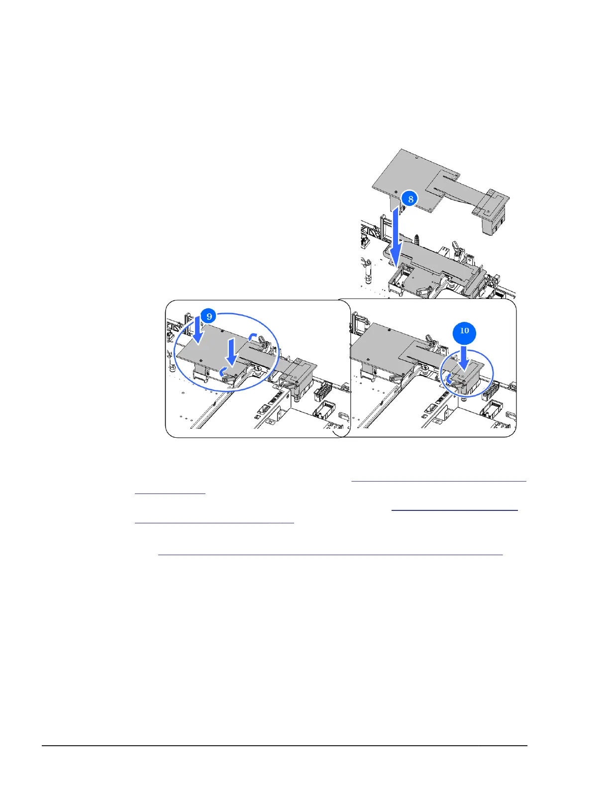
8. Align the connector and guide holes of the connection board of the
connection kit F/H with the male connector and guide pins on the main
board of the server blade, respectively.
9. Push in the connection board into the server blade straight downward by
pushing the portion indicated Push, and then close the two latches.
10. Push in the connector into the PCI expansion blade straight downward by
pushing the portion indicated Push, and then close the latch.
Figure 5-31 Installing connection kit F/H
11. Close the top cover of Server blade. See Closing a top cover, Server blade
on page 5-39 section.
12. Close the top cover of PCI expansion blade. See Closing a top cover, PCI
expansion blade on page 5-41 section.
13. Install the PCI expansion blade.
See
Installing a PCI expansion blade into server chassis on page 5-16
section.
Replacing a PCI expansion blade
The hot-swappable feature of the Hitachi Compute Blade 500 series system
allows a PCI expansion blade replacement with the server chassis power on.
This procedure describes how to replace a PCI expansion blade when the
server chassis power is on.
5-28
Replacing parts
Hitachi Compute Blade 500 Series System Service Manual

 Loading...


