1. Put on an anti-static wrist strap.
2. Connect web console. See Web console login procedure on page 4-3
section.
3. Turn on LID LED for identifying the target module.
See
Identify LED (LID) on/off procedure on page 4-7 section.
4. Turn on the maintenance mode from web console.
See Maintenance mode on/off procedure on page 4-10 section.
5. Identify F/W version and take notes of it.
See F/W version identification procedure on page 4-22 section.
6. If you have the record of switch mode of failed FC switch module, skip
this step.
For confirming the switch mode of FC switch module, see Confirming
switch mode of FC switch module on page 4-25.
7. Back up the configuration data to console PC.
See Backup/restore procedure on page 4-30 section.
8. Power the target switch module off. See Power off the switch module on
page 4-62 section.
9. Remove all cables and SFP+ modules from the failed switch module.
See Removing an SFP+ module on page 5-114 section.
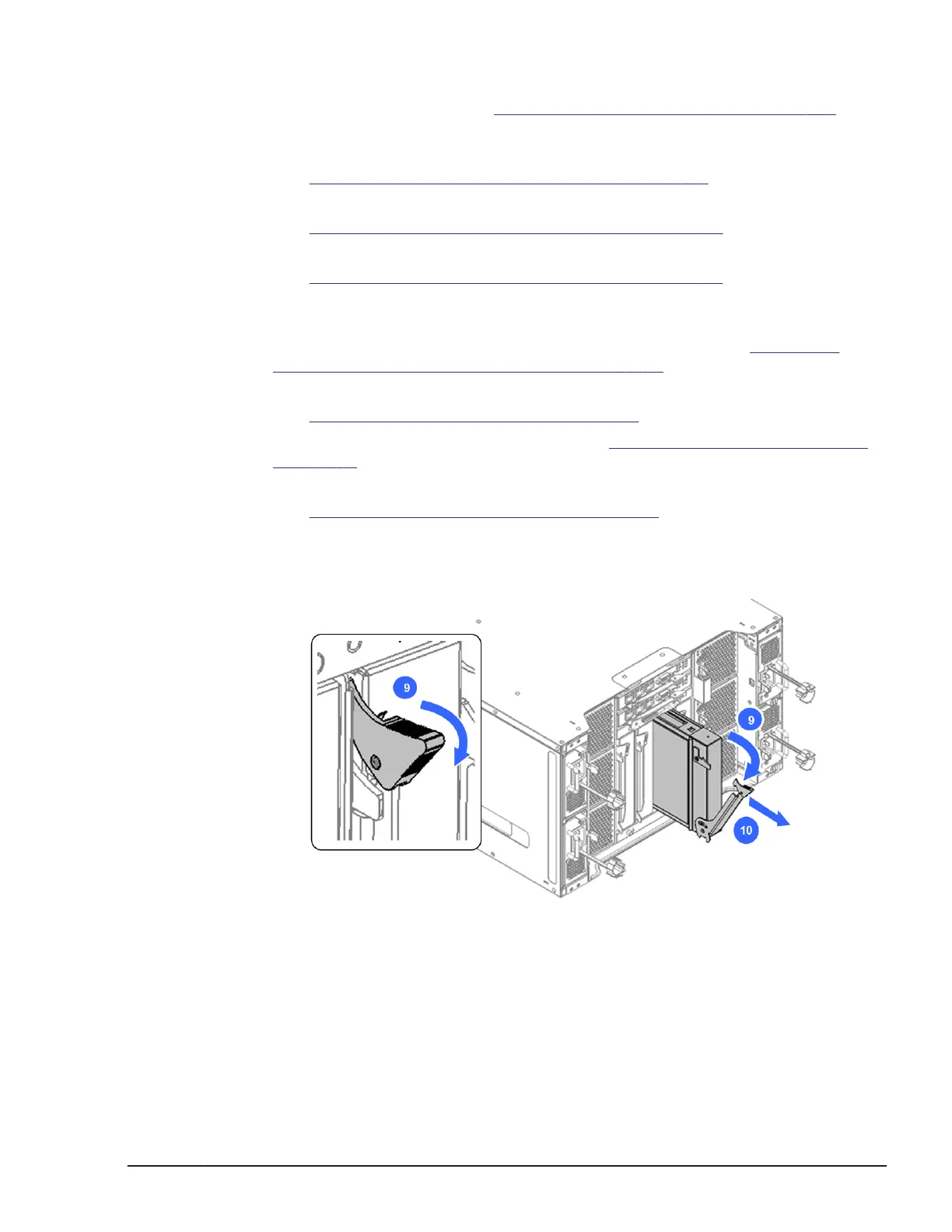
10. Release the blue lock tab and then pull the lever, as shown below.
11. Holding the switch module, carefully slide out the switch module from the
chassis and place it on an anti-static mat.
Figure 5-142 Removing the switch module
Installing a switch module
1. Put on an anti-static wrist strap.
2. Reverse the removal procedure to install the switch module.
Replacing parts
5-111
Hitachi Compute Blade 500 Series System Service Manual

 Loading...


