3. Turn on LID LED for identifying the target module.
See Identify LED (LID) on/off procedure on page 4-7 section.
4. Turn on the maintenance mode from web console.
See Maintenance mode on/off procedure on page 4-10 section.
5. Power the target switch module off. See
Power off the switch module on
page 4-62 section.
6. Remove all cables for the failed module. If SFP+ modules are installed,
remove all of the SFP+ modules. See Removing an SFP+ module on page
5-114 section.
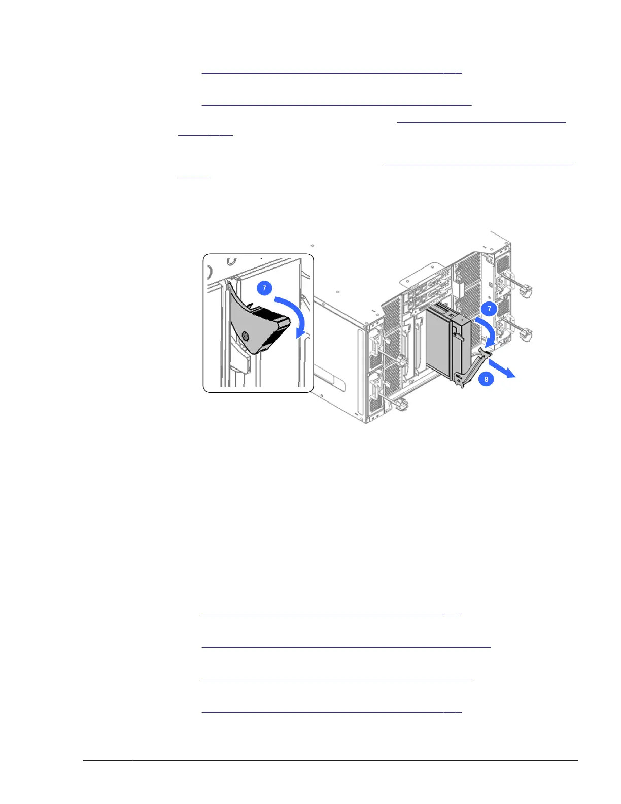
7. Release the blue lock tab and then pull the lever, as shown below.
8. Holding the switch module, carefully slide out the switch module from the
chassis and place it on an anti-static mat.
Figure 5-143 Removing a switch module
Installing a LAN pass through module, LAN pass through module2
1. Put on an anti-static wrist strap.
2. Reverse the removal procedure to install the switch module.
3. Confirm that PWR LED emits in green on the replacing module.
When the 10Gb LAN pass through module inserting, the ST1 LED usually
blinks about 30 to 60 seconds during initialization, and then emits in
green.
4. Turn on LID LED for identifying the target module.
See
Identify LED (LID) on/off procedure on page 4-7 section.
5. Verify that the replacement was successful through the MAR log.
See Alert information identification procedure on page 4-5 section.
6. Turn off the maintenance mode from web console.
See
Maintenance mode on/off procedure on page 4-10 section.
7. Turn off LID LED for identifying the target module.
See Identify LED (LID) on/off procedure on page 4-7 section.
Replacing parts
5-113
Hitachi Compute Blade 500 Series System Service Manual

 Loading...


