4-16
⑤Unscrew two setscrews of the viscometer.
"Caution" The O-ring and squeezing pin may remain in the circulation unit.
Remove them as well.
⑥Attach a new viscometer, and assemble the lead wire and the tube to their original
positions.
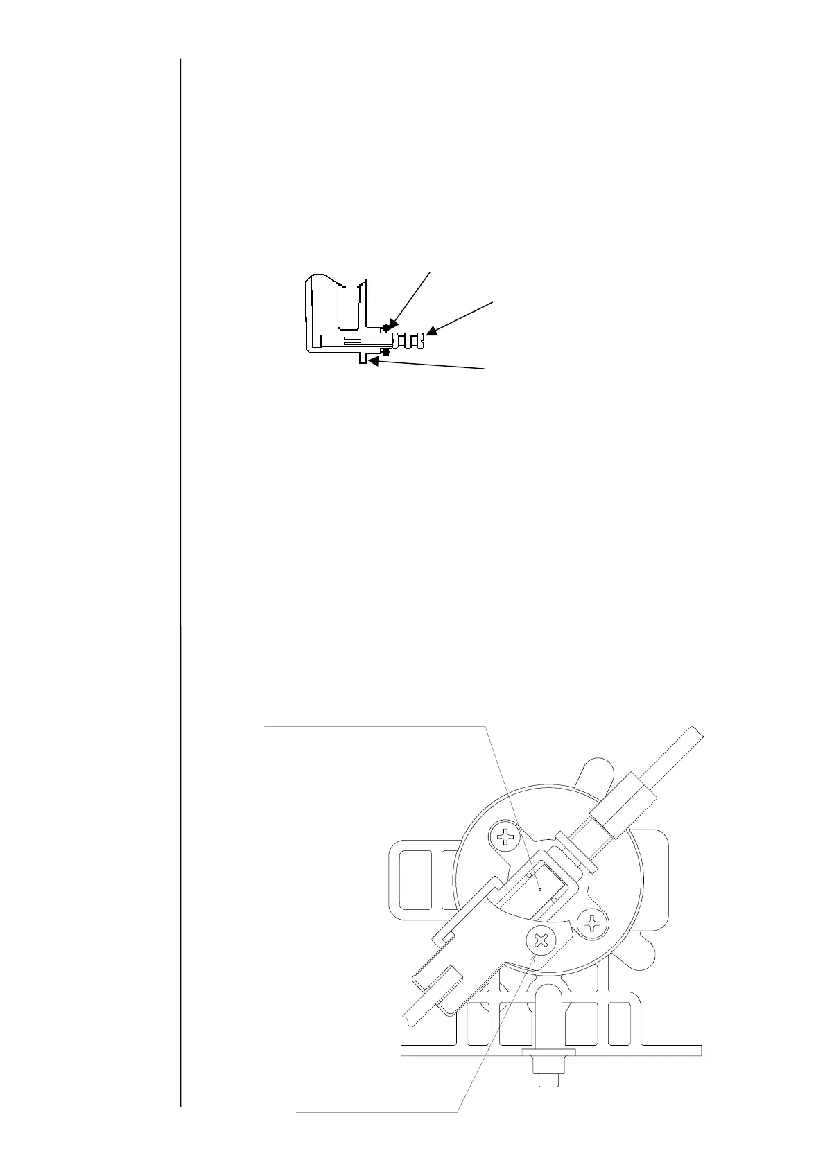
"Caution" Insert and then mount the O-ring and squeezing pin on the
viscometer OUT side as shown below.
⑦Replace it with new ink and perform the viscometer calibration.
(Ref. 2.6 "Calibration of viscometer)
"Caution" In the case where the “viscometer variation abnormality” occurs after
the replacement, there is a possibility of occurrence of leakage on the
viscometer OUT side and mixing of a foreign matter into the
viscometer. In that case, mount them again, and if no recovery is
seen, perform cleaning of the viscometer (4.9(4)).
4.9.3 Replacement of proximity sensor
When the proximity sensor is out of order, the sensor is replaced alone.
"Caution" Turn the power OFF before operation.
①Drain the ink from the main ink tank.
(Ref. "Ink drainage" at "Circulation Control" screen)
②Draw the ink filter so as to bring the viscometer into sight.
③Disconnect the connector of the lead wire of the proximity sensor (4 pins) on the back
surface of this unit.
Proximity sensor (the type display
urf
i
n
th
b
tt
m
Proximity sensor
cover setscrew
O-ring
Squeezing pin
iscometer OUT side