4-17
④Unscrew two setscrews of the viscometer.
⑤Draw the bottom part of the viscometer, unscrew the setscrews of the proximity
sensor cover and take out the proximity sensor.
⑥Put a new proximity sensor into the viscometer.
“Caution” Dispose the proximity sensor so that the type display surface is on the
bottom.
⑦Put the viscometer back in its place and fasten the setscrews of the viscometer.。
⑧Connect the connector of the lead wire of the proximity sensor (4 pins).
⑨Replace it with new ink and perform the viscometer calibration.
(Ref. 2.6 "Calibration of viscometer)
(4) Disassembly and washing of viscometer
When the viscometer is firmly fixed with ink, it is disassembled and washed.
"Caution" Turn the power OFF before operation.
①Remove the viscometer just like 4.9 (2).
②Unscrew the thermistor setscrew and take out the thermistor.
“Caution” Do not directly put the makeup ink over the thermistor.
It causes trouble.
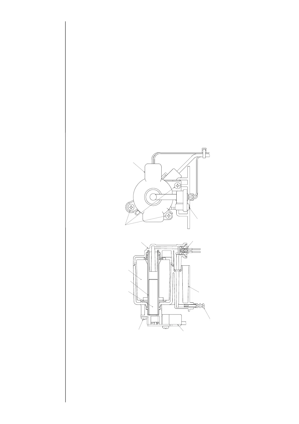
③Unscrew the viscometer cover setscrews and remove the viscometer cover.
④Unscrew the two viscometer IN joint setscrews and take out the cylinder, the plunger
and the coil.
⑤Take out the proximity sensor from the viscometer IN joint just like 4.9 (3).
Viscometer cover
Three viscometer
cover setscrews
Coil
C
linder
Plunger
Two viscometer IN joint setscrews
Thermistor setscrew
Thermistor
Viscometer case
Squeezing pin
Viscometer IN joint
Viscometer cover