Honeywell
3 Installation
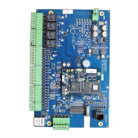
Perform the following steps to install IP-AK2 panel:
Caution
Use a static strap whenever touching the panel to ensure protection from
Electrostatic Discharge (ESD).
1. Check the panel layout, cable runs, and power needs.
2. Mount the enclosure at the proper location on the wall. Use appropriate anchors for
the mounting material.
3. Run all I/O wires to the enclosure, and properly mark each wire for its use (Remove
each terminal plug one at a time to wire the properly labeled cables).
See
Figure 6-1 IP-AK2 Panel Wiring Diagram on page 49. Leave enough shield drain
length to secure to the grounding stud. Also, maintain a distance of at least 6.35mm
between the non-power limited wiring (220VAC/60Hz input wiring, power line filter wiring,
12VDC wiring, and battery backup/charger wiring) and all other wirings.
Caution Do not apply power at this moment.
4. Connect the shield to the grounding studs.
5. Set DIP switch settings for the panel address (see Table 3-5 DIP Switch Settings on
page
12).
6. Check all wirings.
Caution
Improper wiring can cause damage to the IP-AK2 panel when power up and
result in a loss of warranty.
7. Apply power to the panel, and then POWER LED will turn green meanwhile. The
POWER LED is close to 12VDC power connector (TB1). After several minutes,
RUN LED will flash per second. The RUN LED is close to 80-pin Connector (J2).
8. Place one 3.2A-Hr battery in the enclosure. Attach the positive (red) Power Supply-
to-Battery cable to the remaining positive (red) battery terminal; and the negative
(black) Power Supply-to-Battery cable to the remaining negative (black) battery
terminal.
Note
For panels using the Ethernet connection, the cable clamp must be used for the
panel to pass the FCC Part 15 Class B requirements. Snap the clamp around
any portion of the Ethernet cable that is inside of the enclosure.
5