Configuring via IP-AK2 Web Server
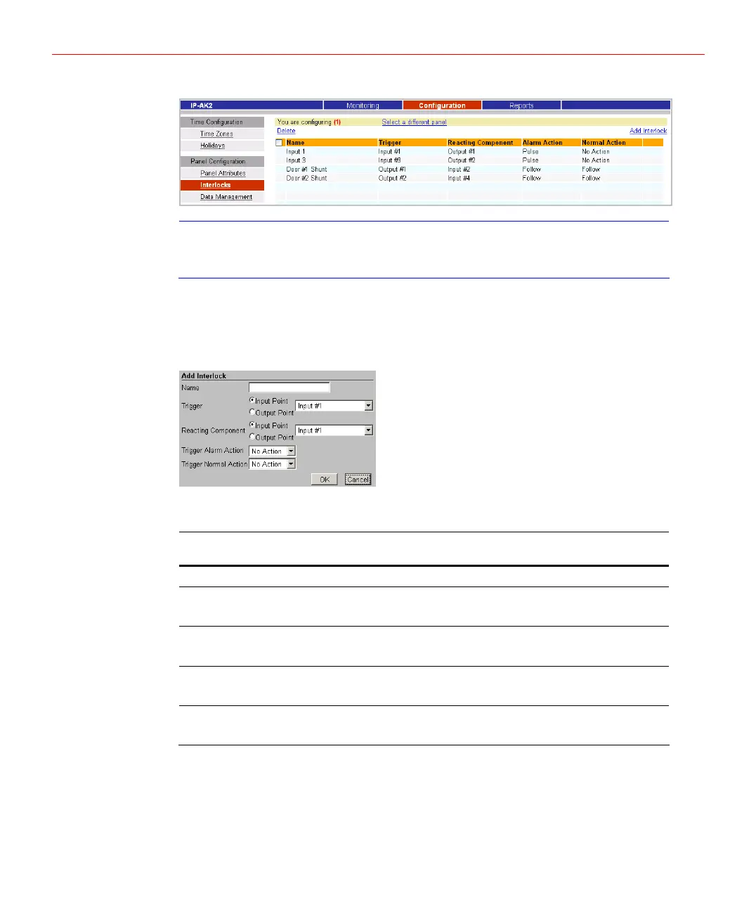
Figure 5-24 Interlocks Page
Note
Some of interlocks can’t be edited or disabled. These interlocks are created
internally to make controls over doors work. They are never supposed to be
changed manually.
Creating Interlock
1. Click【Add Interlock】above the list, the page below will pop up:
Figure 5-25 Add Interlock
2. Refer to the descriptions in the following table to configure each field:
Table 5-2 Interlock Settings Description
Setting Description
Name A unique name identifies the interlock.
Trigger
Specifies the input or output for which a change of state will cause a
reaction from another input, or output. Also, use the drop-down list
to specify the number of the input, or output.
Reacting Component
Specifies the input or output that will react to a change of state from
the trigger point. Also, use the drop-down list to specify the number
of the input, or output.
Trigger Alarm Action
Specifies the reacting component’s action when the trigger’s state is
changed from Normal to Alarm. Select the action from the Upon
Trigger Alarm drop-down list.
Trigger Normal Action
Specifies the reacting component’s action when the trigger’s state is
changed from Alarm to Normal. Select the action from the Upon
Trigger Normal drop-down list.
Modifying Interlock
1. Click the name of the interlock to be modified, the page below will pop up:
26