Installation
Terminal Wire Color Wiegand Reader
TB5-4, 6-4 Black Common
TB5-5, 6-5 Red 12VDC Power
TB5-6, 6-6 Variable Tamper
TB5-7, 6-7 Variable Buzzer
Supervised Input Wiring
The supervised inputs are located on TB5, TB6, TB7 and TB8. Input 1 through Input 4
may be configured for normally open or normally closed contacts as supervised or non-
supervised. Inputs 5 and 6 are on TB8.
Table 3-3 Default Supervised Input Assignments
Terminal Position Input Number Default Function
TB7-1 Input 1 Door 1 REX (Egress)
TB7-3 Input 2 Door 1 Status
TB7-4 Input 3 Door 2 REX (Egress)
TB7-6 Input 4 Door 2 Status
TB8-1 Input 5 Panel Tamper
TB8-3 Input 6 External Power Supply AC FAIL
TB 5-6, 6-6 Input 7/8 Reader Tamper
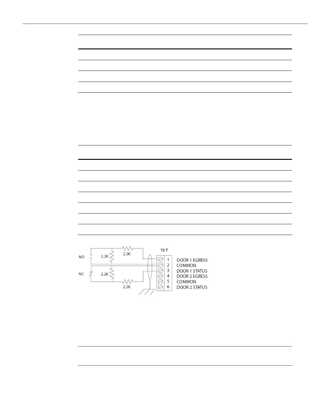
Figure 3-7 Typical Supervised Input Wiring Diagram
The figure above shows the typical wiring for a supervised input using standard 2,200
ohm resistors. The IP-AK2 panel accepts 1,000, 2,200, 4,700, or 10,000 ohm values.
Note that both resistors must have the same value.
In addition, the Panel Tamper and External Power Fail can be supervised and capable of
being used as additional inputs if the default functionality is not needed. They also share
a single common.
Caution
Supervised input wiring must be used if Input 6 is used for “External Power
Supply AC Failed”.
10