65
Common root bridge
The common root bridge is the root bridge of the CIST.
In Figure 18, for example, the common root bridge is a device in MST region 1.
Roles of ports
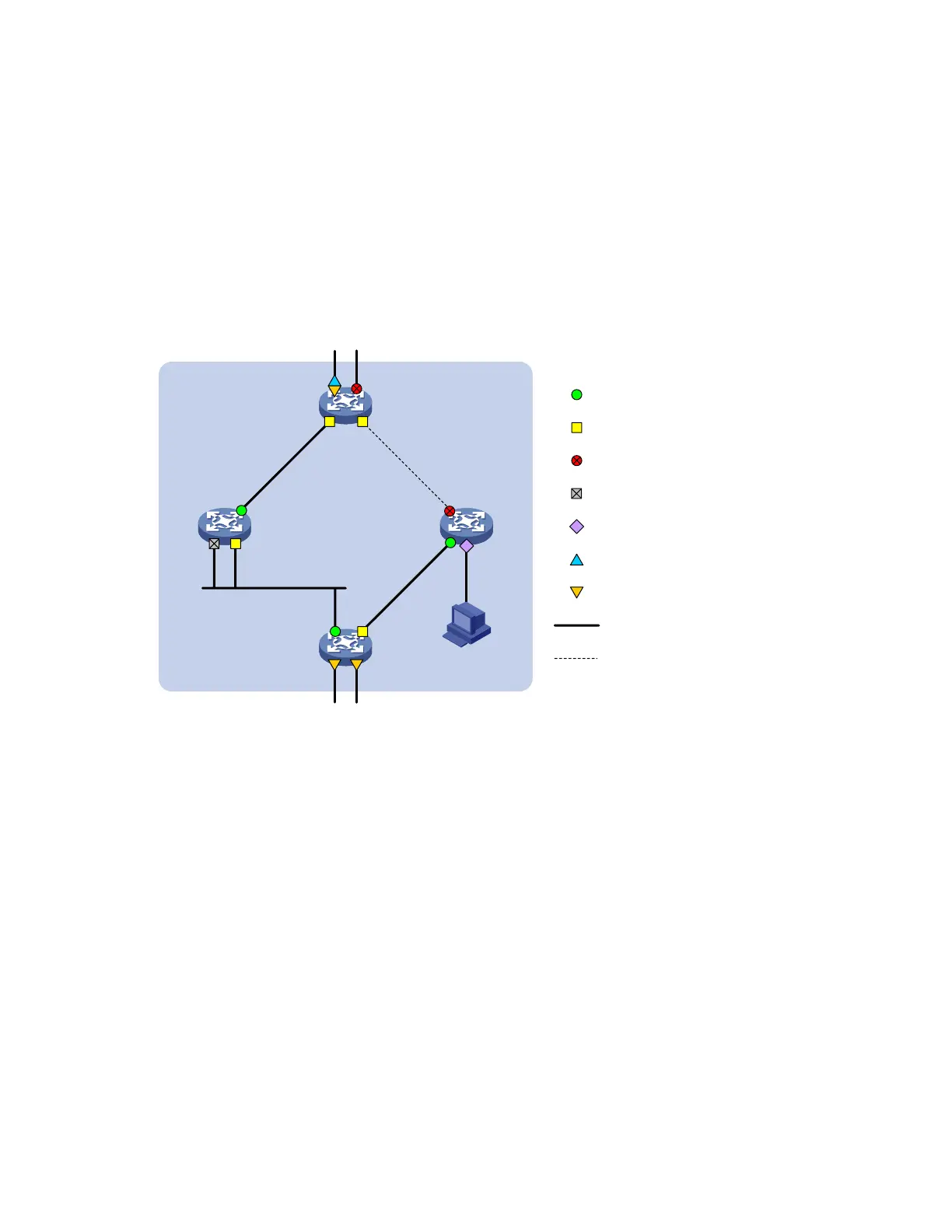
A port can play different roles in different MSTIs. As shown in Figure 20, an MST region comprises
Device A, Device B, Device C, and Device D. Port A1 and port A2 of Device A connect to the common
root bridge. Port B2 and Port B3 of Device B form a loop. Port C3 and Port C4 of Device C connect to
other MST regions. Port D3 of Device D directly connects to a host.
Figure 20 Port roles
Device A
(Root bridge)
Port A1 Port A2
Root port
Designated port
Normal link
Blocked link
Alternate port
Backup port
Master port
Boundary port
Device C
Device B Device D
Port A3 Port A4
Port B1
Port B2 Port B3
Port C1
Port C2
Port C3 Port C4
Port D1
Port D2
MST region
To the common root
To other MST regions
Edge port
Port D3
MSTP calculation involves the following port roles:
Root port: Forwards data for a non-root bridge to the root bridge. The root bridge does not have
any root port.
Designated port: Forwards data to the downstream network segment or device.
Alternate port: The backup port for a root port or master port. When the root port or master port is
blocked, the alternate port takes over.
Backup port: The backup port of a designated port. When the designated port fails, the backup port
takes over. When a loop occurs because of the interconnection of two ports of the same MSTP
device, the device blocks either of the two ports, and the blocked port is the backup port.
Edge port: An edge port does not connect to any network device or network segment, but directly
connects to a user host.
Master port: A port on the shortest path from the local MST region to the common root bridge. The
master port is a root port on the IST or CIST and still a master port on the other MSTIs.
Boundary port: Connects an MST region to another MST region or to an STP/RSTP-running device.
In MSTP calculation, a boundary port’s role on an MSTI is consistent with its role on the CIST. But
that is not true with master ports. A master port on MSTIs is a root port on the CIST.

 Loading...


