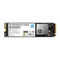
Figure 3 P6000 EVA FC controller enclosure (rear view)
9. Enclosure power push button1. Power supply 1
10. Power supply 22. Controller 1
11. DP-A and DP-B, connection to back end (storage)3. Management module status LEDs
12. FP1 and FP2, connection to front end (host or SAN)4. Ethernet port
13. FP3 and FP4, connection to front end (host or SAN)5. Management module
14. Manufacturing diagnostic port6. Controller 2
15. Controller status and fault LEDs7. Rear UID push button
8. Enclosure status LEDs
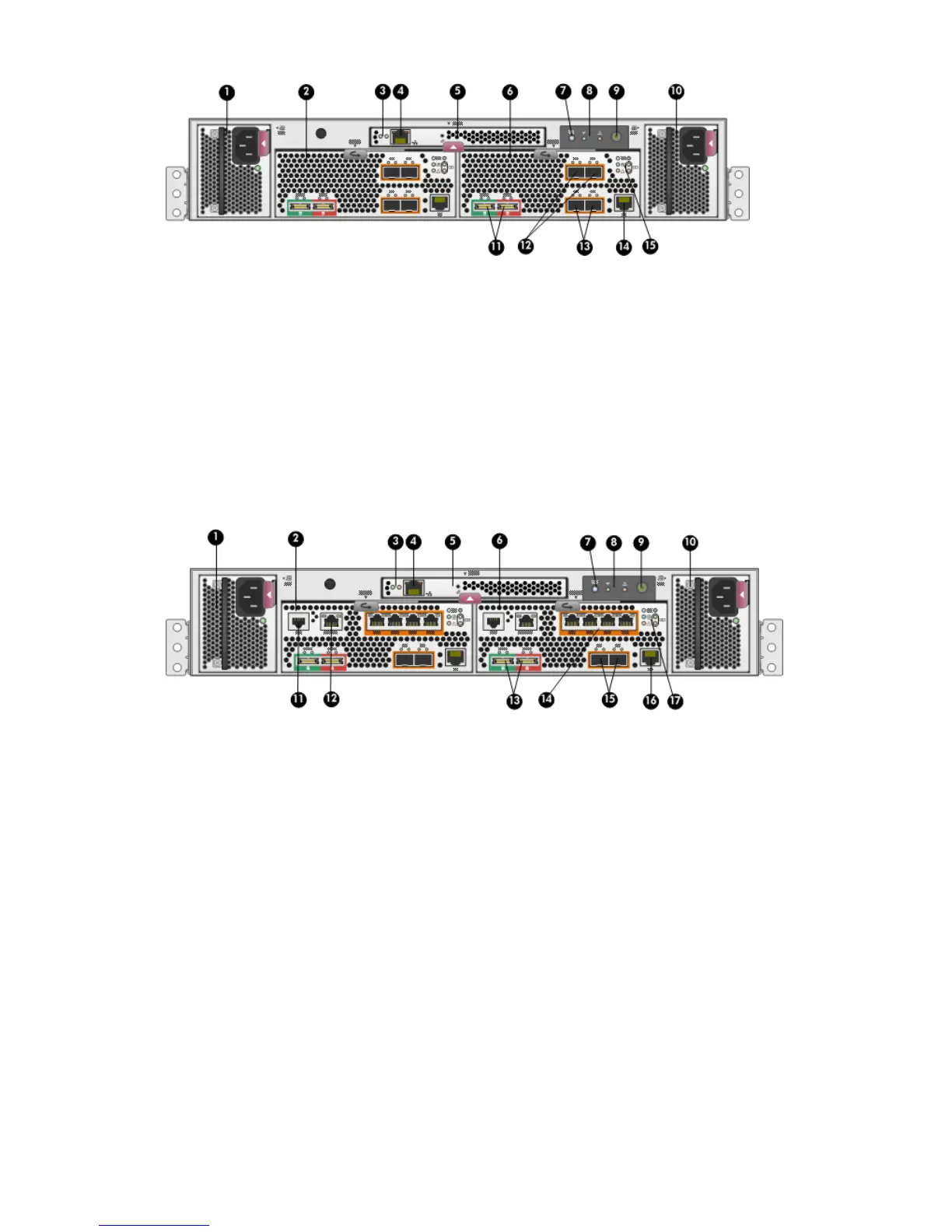
Figure 4 P6000 EVA FC-iSCSI controller enclosure (rear view)
10. Power supply 21. Power supply 1
11. Serial port2. Controller 1
12. SW Management port3. Management module status LEDs
13. DP-A and DP-B, connection to back-end (storage)4. Ethernet port
14. 1GbE ports 1–45. Management module
15. FP3 and FP4, connection to front end (host or SAN)6. Controller 2
16. Manufacturing diagnostic port7. Rear UID push button
17. Controller status and fault LEDs8. Enclosure status LEDs
9. Enclosure power push button
Controller enclosure 23